


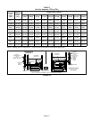

Page 29
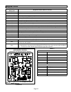
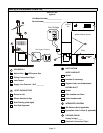
HEAT FAN‐OFF TIME IN SECONDS
To adjust fan-off timing, reposition jumper across pins to
achieve desired setting.
NO JUMPER
FIGURE 32
60
90
120
180
60
90
120
180
60
90
120
180
60
90
120
180
60 Second
off Time
90 Second
off Time
120 Second
off Time
180 Second
off Time
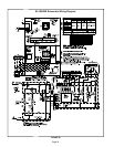
Constant Torque Motor
EL180UHE units are equipped with a constant torque ECM
motor. It has a DC motor coupled to an electronic control
module both contained in the same motor housing. The mo
tor is programmed to provide constant torque at each of the
five selectable speeds. The motor has five speed taps.
Each tap requires 24 volts to energize.
Input Voltage Requirements
The circuit is designed to be operated with AC voltage. A
voltage of 12 to 33VAC is required to energize the motor.
Expected current draw will be less than 20mA.
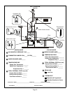
Blower Speeds
Follow the steps below to change the blower speeds.
1 - Turn off electrical power to furnace.
2 - Remove blower access panel.
3 - Disconnect existing speed tap at integrated control
speed terminal.
NOTE - Termination of any unused motor leads must be
insulated.
4 - Place unused blower speed tap on integrated control
“PARK” terminal or insulate.
5 - Refer to blower speed selection chart on unit wiring dia
gram for desired heating or cooling speed. See Product
Specifications manual for blower performance data.
6 - Connect selected speed tap at integrated control
speed terminal.
7 - Resecure blower access panel.
8 - Turn on electrical power to furnace.
9 - Recheck temperature rise.
Electronic Ignition
The integrated control has an added feature of an internal
Watchguard control. The feature serves as an automatic re
set device for integrated control lockout caused by ignition
failure. This type of lockout is usually due to low gas line
pressure. After one hour of continuous thermostat demand
for heat, the Watchguard will re-set and remake thermostat
demand to the furnace and automatically reset the inte
grated control to begin the ignition sequence.
Service
WARNING
ELECTRICAL SHOCK, FIRE,
OR EXPLOSION HAZARD.
Failure to follow safety warnings exactly could result
in dangerous operation, serious injury, death or
property damage.
Improper servicing could result in dangerous opera
tion, serious injury, death, or property damage.
Before servicing, disconnect all electrical power to
furnace.
When servicing controls, label all wires prior to dis
connecting. Take care to reconnect wires correctly.
Verify proper operation after servicing.
At the beginning of each heating season, a qualified techni
cian should check the system as follows:
Blower
Check the blower wheel for debris and clean if necessary.
The blower motors are prelubricated for extended bearing
life. No further lubrication is needed.
WARNING
The blower access panel must be securely in place
when the blower and burners are operating. Gas
fumes, which could contain carbon monoxide, can
be drawn into living space resulting in personal inju
ry or death.
Filters
All EL180UHE filters are installed external to the unit. Fil
ters should be inspected monthly. Clean or replace the fil
ters when necessary to ensure that the furnace operates
properly. Replacement filters must be rated for high veloc
ity airflow. Table 1 lists recommended filter sizes.
Flue And Chimney
1 - Check flue pipe, chimney and all connections for tight
ness and to make sure there is no blockage.
2 - Check unit for proper draft.
Electrical
1 - Check all wiring for loose connections.
2 - Check for the correct voltage at the furnace (furnace
operating). Correct voltage is 120VAC +
10%.
3 - Check amp-draw on the blower motor with blower ac
cess panel in place.
Unit Nameplate__________Actual__________
Cleaning the Burners
NOTE - Use papers or protective covering in front of the fur
nace during cleaning.
1 - Turn off both electrical and gas power supplies to fur
nace.