


Page 11
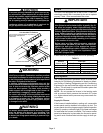
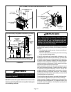
CAUTION
If this unit is being installed in a space serviced by
an exhaust fan, power exhaust fan, or other device
which may create a negative pressure in the space,
take care when sizing the inlet air opening. The in
let air opening must be sized to accommodate the
maximum volume of exhausted air as well as the
maximum volume of combustion air required for
all gas appliances serviced by this space.
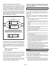
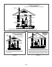
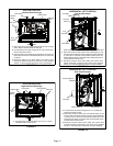
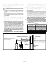
Horizontal Application
Unit Installed on Platform
FIGURE 13
clearances.
GAS
ENTRY
VENT
PIPE
See the unit nameplate for
Line contact is permissible but not preferred
SERVICE PLATFORM
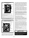
WARNING
Improper installation of the furnace can result in per
sonal injury or death. Combustion and flue products
must never be allowed to enter the return air system
or the living space. Use screws and joint tape to seal
the return air system to the furnace.
In platform installations with bottom return air, the
furnace should be sealed airtight to the return air ple
num. A door must never be used as a portion of the
return air duct system. The base must provide a
stable support and an airtight seal to the furnace. Al
low absolutely no sagging, cracks, gaps, etc.
The return and supply air duct systems must never
be connected to or from other heating devices such
as a fireplace or stove, etc. Fire, explosion, carbon
monoxide poisoning, personal injury and/or proper
ty damage could result.
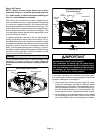
WARNING
The blower access panel must be securely in place
when the blower and burners are operating. Gas
fumes, which could contain carbon monoxide, can
be drawn into living space resulting in personal inju
ry or death.
Filters
This unit is not equipped with a filter or rack. A field-pro
vided high-velocity filter is required for the unit to operate
properly. Table 1 lists recommended filter sizes.
IMPORTANT
If a highefficiency filter is being installed as part of
this system to ensure better indoor air quality, the fil
ter must be properly sized. Highefficiency filters
have a higher static pressure drop than standardef
ficiency glass/foam filters. If the pressure drop is too
great, system capacity and performance may be re
duced. The pressure drop may also cause the limit to
trip more frequently during the winter and the indoor
coil to freeze in the summer, resulting in an increase
in the number of service calls.
Before using any filter with this system, check the
specifications provided by the filter manufacturer
against the data given in the appropriate Lennox
Product Specifications bulletin. Additional informa
tion is provided in Service and Application Note
ACC002 (August 2000).
A filter must be in place any time the unit is operating.
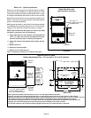
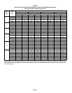
TABLE 1
Furnace
Cabinet Width
Filter Size
Side Return Bottom Return
A - 14-1/2” 16 X 25 X 1 (1) 14 X 25 X 1 (1)
B - 17-1/2” 16 X 25 X 1 (1) 16 X 25 X 1 (1)
C - 21” 16 X 25 X 1 (1) 20 X 25 X 1 (1)
D - 24-1/2” 16 X 25 X 1 (2) 24 X 25 X 1 (1)
Duct System
Use industry‐approved standards (such as those pub
lished by Air Conditioning Contractors of America or Ameri
can Society of Heating, Refrigerating and Air Conditioning
Engineers) to size and install the supply and return air duct
system. This will result in a quiet and low‐static system that
has uniform air distribution.
NOTE - Do not operate the furnace in the heating mode
with an external static pressure that exceeds 0.5 inches
w.c. Higher external static pressures may cause erratic lim
it operation.
Supply Air Plenum
If the furnace is installed without a cooling coil, a removable
access panel must be installed in the supply air duct. The
access panel should be large enough to permit inspection
(either by smoke or reflected light) of the heat exchanger
for leaks after the furnace is installed. The furnace access
panel must always be in place when the furnace is operat
ing and it must not allow leaks into the supply air duct sys
tem.