


Page 65
Integrated Control Diagnostic Codes (continued)
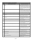
Code Diagnostic Codes/Status of Equipment Action Required to Clear and Recover
E 312
Restricted air flow in cooling or continuous fan mode is lower than cfm
setting.
Warning Only. Restricted airflow − Indoor blower is
running at a reduced CFM (Cutback Mode − The
variable speed motor has pre−set speed and torque
limiters to protect the motor from damage caused
by operating outside of design parameters (0 to 0.8"
W.C.. total external static pressure). Check filter and
duct system. To clear, replace filter if needed or re-
pair/add duct. Cleared after the current service de-
mand is satisfied.
E 313
Indoor or outdoor unit capacity mismatch. Communication only. Incorrect indoor/outdoor capacity code selected.
Check for proper configuring in installation instruc-
tions. Alarm is just a warning. The system will oper-
ate, but might not meet efficiency and capacity pa-
rameters. Alarm will clear when commissioning is
exited. Cleared after commissioning is complete.
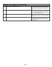
E 331
Global network connection − Communication link problem. For Future Use.
E 334
Relay Y1" stuck on interated control. Replace integrated control.
E 347
No 24 Volt output on Y1 of "integrated control" with non communicating
outdoor unit.
Operation stopped. Y1 relay / Stage 1 failed. (Pilot
relay contacts did not close or the relay coil did not
energize; no input back to IFC chip). Critical Alert.
Cleared after reset and Y1 input sensed.
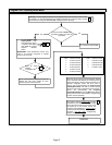
E 348
No 24 Volt output on Y2 of "integrated control" with non?communicating
outdoor unit.
Y2 relay / Stage 2 failed. (Pilot relay contacts did
not close or the relay coil did not energize; no input
back to IFC chip). Critical Alert. Cleared after reset
and Y1 input sensed.
E 349
No 24 Volts between R & O on "integrated control" with non communi-
cating outdoor unit (Dual fuel module required for heat pump application).
Configuration link R to O needs to be restored. Re-
place link or hard−wire. Applicable in non communi-
cating mode. Critical Alert.
E 370
Interlock switch sensed open for 2 minutes. Control sees the loss of 24VAC for 2 minutes .Ter-
minate all services and wait for interlock switch to
close. The alarm will clear when 24VAC is continu-
ously sensed on DS terminal for a minimum of 10
seconds or on a power reset.
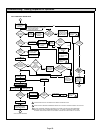
E 400
LSOM − Compressor internal overload tripped. Thermostat demand Y1 is present; but, compressor
is not running. Check power to outdoor unit. Clears
the error after current is sensed in both RUN and
START sensors for at least 2 seconds, or after ser-
vice is removed, or after power reset.
E 401
LSOM Compressor long run cycle or low system pressure. Compressor ran more than 18 hours to satisfy a
single thermostat demand. Critical Alert. Clears the
error after 30 consecutive normal run cycles or
power reset. Also monitors low pressure switch
trips.
E 402
LSOM − Outdoor unit system pressure trip. Discharge or suction pressure out−of−limits, or com-
pressor overloaded. Clears the error after 4 consec-
utive normal compressor run cycles.
E 403
LSOM − Compressor short−cycling. .(Running less than 4 minutes). Out-
door unit pressure trip
Compressor runs less than 3 minutes to satisfy a
thermostat demand. Clears the error after 4 consec-
utive normal run cycles or power reset.
E 404
LSOM − Compressor rotor locked. Compressor short−cycling. (Running
less than 4 minutes).
Compressor rotor locked up due to run capacitor
short, bearings are seized, excessive liquid refriger-
ant, etc. Clears the error after 4 consecutive normal
run cycles or after power reset.
E 405
LSOM − Compressor open circuit. Compressor circuit open (due to power disconnec-
tion, open fuse, etc.) Clears the error after 1 normal
compressor run cycle.