


Page 32
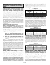
TABLE 11
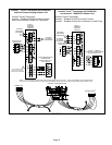
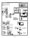
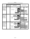
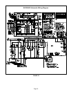
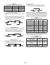
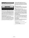
SL280 Field Wiring Applications With Conventional Thermostat (Continued)
Thermostat
DIP Switch Settings and On−Board Links (figure 34)
Wiring Connections
DIP Switch 1
Thermostat
Heating
Stages
On Board Links Must Be Cut To Select
System Options
Dual Fuel
Single Stage
Heat Pump
ComfortSense
7000 L7724U
thermostat w/
dual fuel capa-
bilities
Capable of 2
stage gas heat
control w/dehu-
midification
control
OFF
CUT ON−BOARD LINK
W951
HEAT
PUMP
CUT ON−BOARD LINK
W914
DEHUM
OR
HARMONY
L7724U
T’STAT
FURNACE
TERM. STRIP
HEAT PUMP
67M41*
Y
H
L
Y2
D
B
L
Y2
T
T
outdoor
sensor
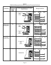
Dual Fuel
Two Stage
Heat Pump
ComfortSense
7000 L7724U
thermostat w/
dual fuel capa-
bilities
Capable of 2
stage gas heat
control w/dehu-
midification
OFF
CUT ON−BOARD LINK
W914
DEHUM
OR
HARMONY
CUT ON−BOARD LINK
W951
HEAT
PUMP
CUT ON−BOARD LINK
W915
2 STAGE
COMPR
L7724U
T’STAT
FURNACE
TERM. STRIP
HEAT PUMP
67M41*
H
L
Y2
D
B
L
Y2
T
T
outdoor
sensor
Y2
out blue
* Connect W1 to W1 ONLY if using defrost tempering kit 67M41
NOTE − Do NOT make a wire connection between the room thermostat L terminal and the L terminal of the SL280
integrated control.