


Page 57
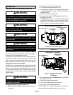
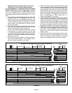
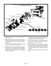
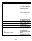
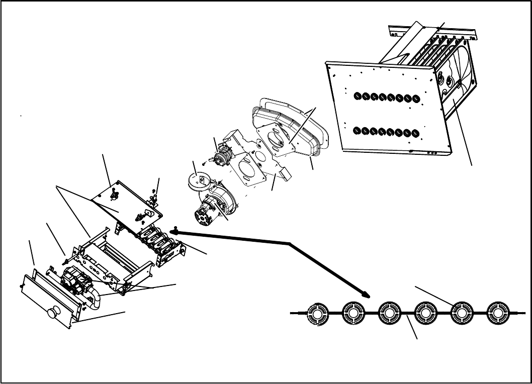
SL280UHV BURNER, COMBUSTION AIR INDUCER ASSEMBLY &
HEAT EXCHANGER REMOVAL
FIGURE 39
heat exchanger
gasket
collector box
orifice plate
flue transition
pressure switch
combustion air inducer
burners
burner box assembly
burner box cover plate
manifold and gas valve
gasket
retention rings
cross over
ignitor
rollout switch
sensor
9 − Remove screws from both sides, top and bottom of
vestibule panel.
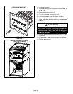
10− Remove heat exchanger. It may be necessary to
spread cabinet side to allow more room. If so, remove
five screws from the left side or right side of cabinet.
See figure 41.
11− Back wash using steam. Begin from the burner opening
on each clam. Steam must not exceed 275°F.
12− To clean burners, run a vacuum cleaner with a soft brush
attachment over the face of burners. Visually inspect in-
side the burners and crossovers for any blockage
caused by foreign matter. Remove any blockage. Figure
39 shows burner detail.
13− To clean the combustion air inducer visually inspect and
using a wire brush clean where necessary. Use com-
pressed air to clean off debris and any rust.
14− Reinstall heat exchanger in vestibule. (Replace the
five screws in the cabinet from step 10 if removed).
15− NOX units only − replace NOX inserst.
16− Reinstall collector box and combustion air assembly.
Reinstall all screws to the collector box and combustion
air inducer. Failure to replace all screws may cause
leaks. Inspect gaskets for any damage and replace if
necessary.
17− Reinstall burner box, manifold assembly and burner box
cover.