


Page 25
Electrical
ELECTROSTATIC DISCHARGE (ESD)
Precautions and Procedures
CAUTION
Electrostatic discharge can affect elec-
tronic components. Take precautions to
neutralize electrostatic charge by
touching your hand and tools to metal
prior to handling the control.
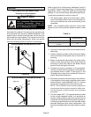
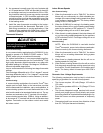
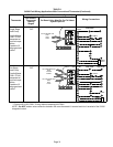
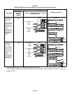
The unit is equipped with a field make−up box on the left
hand side of the cabinet. The make−up box may be moved
to the right side of the furnace to facilitate installation. If the
make−up box is moved to the right side, clip the wire ties
that bundle the wires together. The excess wire must be
pulled into the blower compartment. Secure the excess
wire to the existing harness to protect it from damage.
INTERIOR MAKE−UP BOX INSTALLATION
FIGURE 28
BOX
Left side
INTERIOR MAKE−UP BOX INSTALLATION
FIGURE 29
BOX
Right Side
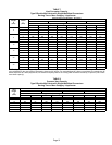
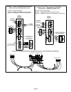
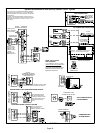
Refer to figure 33 for unit field wiring. See figures 30 and 31
for icomfort Touch
®
thermostat wiring in communicating
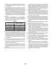
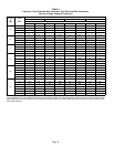
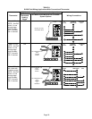
applications. Table 11 shows DIP switch and on−board link
settings for non−communicating thermostat applications.
Typical wiring schematic is shown in figure 32.
1 − The power supply wiring must meet Class I restric-
tions. Protected by either a fuse or circuit breaker, se-
lect circuit protection and wire size according to unit
nameplate.
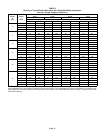
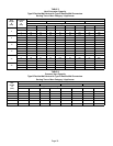
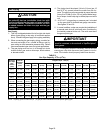
NOTE − Unit nameplate states maximum current draw.
Maximum over−current protection allowed is shown in table
10.
TABLE 10
SL280UH Model
Maximum Over−Current
Protection (Amps)
070V36A, 09036B 15
090V48B, 090V60C, 110V60C,
135V60D
20
2 − Holes are on both sides of the furnace cabinet to facili-
tate wiring.
3 − Install a separate (properly sized) disconnect switch
near the furnace so that power can be turned off for
servicing.
4 − Before connecting the thermostat or the power wiring,
check to make sure the wires will be long enough for
servicing at a later date. Remove the blower access
panel to check the length of the wire.
5 − Complete the wiring connections to the equipment.
Use the provided unit wiring diagram and the field wir-
ing diagrams shown in table 11 and figure 33. Use
18−gauge wire or larger that is suitable for Class II ra-
ting for thermostat connections.
6 − Electrically ground the unit according to local codes or,
in the absence of local codes, according to the current
National Electric Code (ANSI/NFPA No. 70). A green
ground wire is provided in the field make−up box.
NOTE − The SL280UHV furnace contains electronic
components that are polarity sensitive. Make sure
that the furnace is wired correctly and is properly
grounded.
7 − One line voltage ACC" 1/4" spade terminal is provided
on the furnace integrated control. Any electronic air
cleaner or other accessory rated up to one amp can be
connected to this terminal with the neutral leg of the cir-
cuit being connected to the one of the provided neutral
terminals. See figure 34 for control configuration. This
terminal is energized when the indoor blower is operat-
ing.