


Page 51
Unit Start−Up
FOR YOUR SAFETY READ BEFORE LIGHTING
WARNING
Do not use this furnace if any part has been underwa-
ter. Immediately call a licensed professional service
technician (or equivalent) to inspect the furnace and
to replace any part of the control system and any gas
control which has been under water.
WARNING
If overheating occurs or if gas supply fails to shut off,
shut off the manual gas valve to the appliance before
shutting off electrical supply.
CAUTION
Before attempting to perform any service or mainte-
nance, turn the electrical power to unit OFF at dis-
connect switch.
WARNING
During blower operation, the ECM motor emits ener-
gy that may interfere with pacemaker operation. In-
terference is reduced by both the sheet metal cabinet
and distance.
BEFORE LIGHTING smell all around the appliance area for
gas. Be sure to smell next to the floor because some gas is
heavier than air and will settle on the floor.
The gas valve on the SL280UHV unit will be equipped with
a gas control switch. Use only your hand to move the
switch. Never use tools. If the switch will not turn or if the
control switch will not move by hand, do not try to repair it.
Placing the furnace into operation:
SL280UHV units are equipped with an automatic ignition
system. Do not attempt to manually light burners on these
furnaces. Each time the thermostat calls for heat, the
burners will automatically light. The ignitor does not get
hot when there is no call for heat on units with an automatic
ignition system.
WARNING
If you do not follow these instructions exactly, a fire
or explosion may result causing property damage,
personal injury or death.
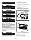
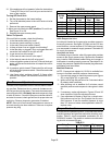
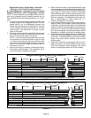
Gas Valve Operation (Figures 35 and 36)
1 − STOP! Read the safety information at the beginning of
this section.
2 − Set the thermostat to the lowest setting.
3 − Turn off all electrical power to the unit.
4 − This furnace is equipped with an ignition device which
automatically lights the burners. Do not try to light the
burners by hand.
5 − Remove the upper access panel.
6 − Move gas valve switch to OFF position. Do not force.
See figure 35 or 36.
7 − Wait five minutes to clear out any gas. If you then smell
gas, STOP! Immediately call your gas supplier from a
neighbor’s phone. Follow the gas supplier’s instruc-
tions. If you do not smell gas go to next step.
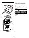
GAS VALVE SHOWN IN ON POSITION
INLET PRESSURE POST
HIGH FIRE ADJUSTMENT
SCREW
(under cap)
MANIFOLD
PRESSURE TAP
WHITE RODGERS GAS VALVE
FIGURE 35
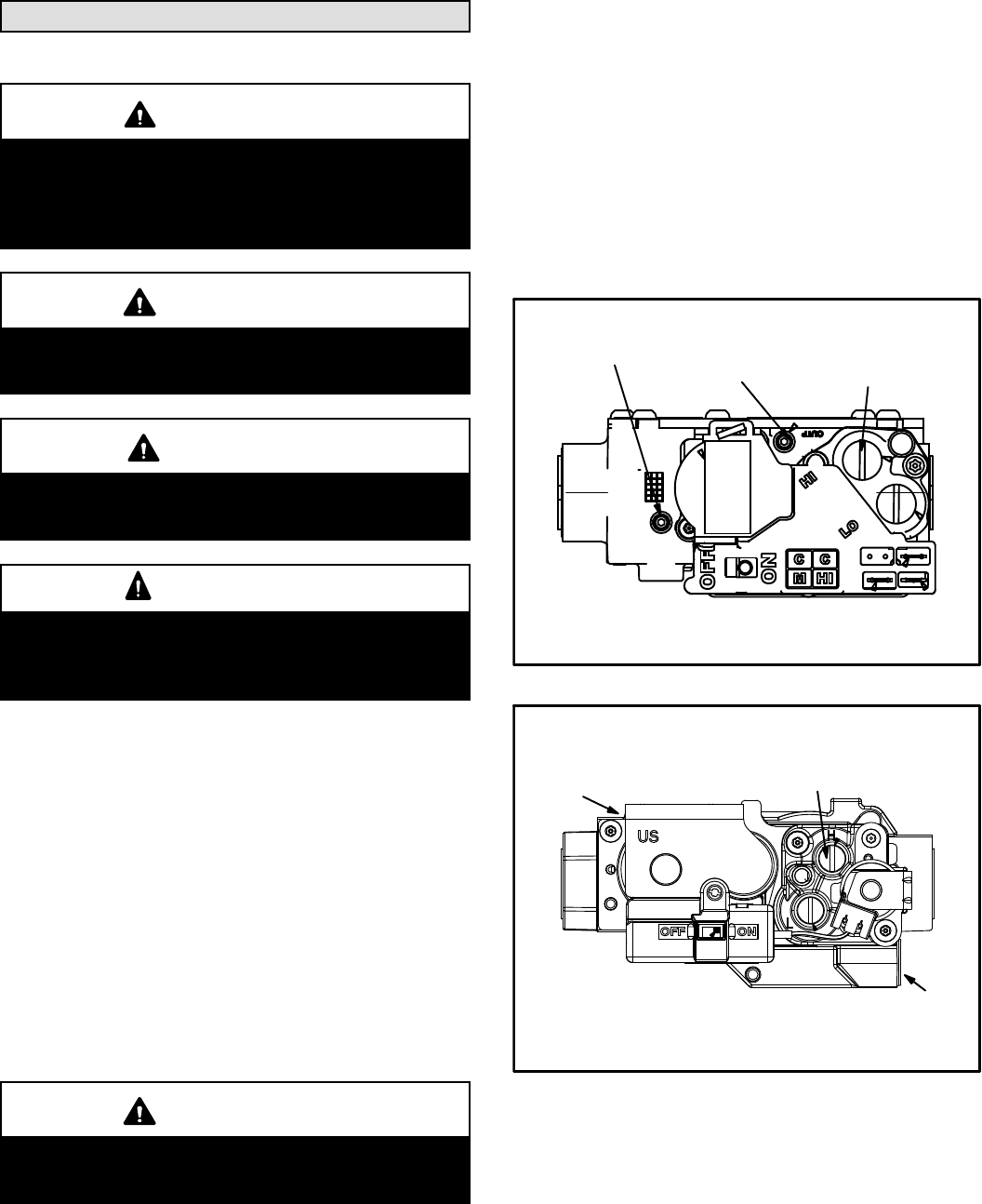
GAS VALVE SHOWN IN ON POSITION
MANIFOLD
PRESSURE
TAP ON
SIDE
HIGH FIRE
ADJUSTING SCREW
(under cap)
INLET PRESSURE TAP
ON SIDE
HONEYWELL GAS VALVE
FIGURE 36
8 − Move gas valve switch to ON position. Do not force.
See figure 35 or 36.
9 − Replace the upper access panel.
10− Turn on all electrical power to to the unit.
11− Set the thermostat to desired setting.
NOTE − When unit is initially started, steps 1 through 11
may need to be repeated to purge air from gas line.