


Page 26
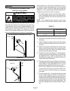
8 − An unpowered, normally open (dry) set of contacts with
a 1/4" spade terminal HUM" are provided for humidifi-
er connections and may be connected to 24V or 120V.
Any humidifier rated up to one amp can be connected
to these terminals. In 120V humidifier applications the
neutral leg of the circuit can be connected to one of the
provided neutral terminals. This terminal is energized
in the heating mode.
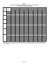
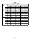
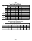
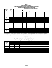
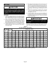
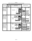
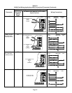
9 − Install the room thermostat according to the instruc-
tions provided with the thermostat. See table 11 for
field wiring connections in varying applications. If the
furnace is being matched with a heat pump, refer to the
instruction packaged with the dual fuel thermostat.
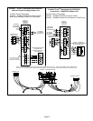
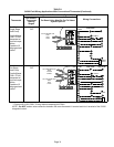
Thermostat Selection
CAUTION
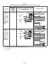
Field wiring for both communicating and non−com-
municating applications is illustrated in diagrams,
which begin on Page 27.
Non−Communicating
In non−communicating applications the SL280UHV is de-
signed to operate in a SINGLE−STAGE mode or TWO−
STAGE mode using a conventional thermostat.
For optimal performance in non−communicating applica-
tions, Lennox recommends use of a ComfortSense
®
7000
high quality electronic digital thermostat or any other with
adjustable settings for 1st stage / 2nd stage on / off differen-
tials and adjustable stage timers.
Lennox recommends the following two−stage thermostat
settings:
First heat stage differential set to 1/2 to 1 degree F; second
heat stage differential set to 1/2 or 1 degree F; second heat
stage upstage timer disabled, or set to maximum (1 hr mini-
mum).
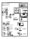
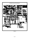
Communicating
In communicating applications the icomfort Touch
®
ther-
mostat must be used. Refer to the instructions provided
with the thermostat for installation, set−up and operation. In
communicating system all unused thermostat wire in the
wire bundle needs to be terminated inside and out. The ex-
tra wires can terminate on the ’C" terminal of the icomfortt
communication terminal strip. (RSBus). Using an addition-
al wire come off "C" terminal and wire nut all the extra wires
together. Termination on the outdoor control must match
the indoor control.
Indoor Blower Speeds
Non−Communicating
1 − When the thermostat is set to FAN ON," the indoor
blower will run continuously at a field selectable per-
centage of the second−stage cooling speed when there
is no cooling or heating demand. The factory default
setting is 38% of cool speed.
2 − When the SL280UHV is running in the heating mode,
the indoor blower will run on the heating speed desig-
nated by the positions of DIP switches 11, 12 and 13.
First stage heating will run at 91% heat speed.
3 − When there is a cooling demand, the indoor blower will
run on the cooling speed designated by the positions
of DIP switches 5 and 6. First stage cooling will run at
70% cool speed.
Communicating
NOTE − When the SL280UHV is used with icomfort
Touch
®
thermostat, proper indoor blower speed selec-
tions are made by the communicating thermostat.
1 − When the thermostat is set to FAN ON," the indoor
blower will run at setting determined during system
configuration.
2 − When there is a heating demand the fan will run on
heating speeds for firing rate.
3 − When there is a cooling demand, the fan will run on the
first stage and second stage cooling speed set using
the icomfort Touch® thermostat in the installer setup
mode. The factory default is based upon 400 CFM a
ton.
Generator Use − Voltage Requirements
The following requirements must be kept in mind when
specifying a generator for use with this equipment:
S The furnace requires 120 volts (Range: 102 volts to
132 volts)
S The furnace operates at 60 Hz +
5% (Range: 57 Hz to
63 Hz)
S The furnace integrated control requires both correct
polarity and proper ground. Both polarity and proper
grounding should be checked before attempting to op-
erate the furnace on either permanent or temporary
power
S Generator should have a wave form distortion of less
than 5% THD (total harmonic distortion)