


Page 14
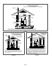
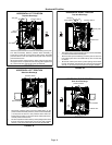
Horizontal Position
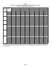
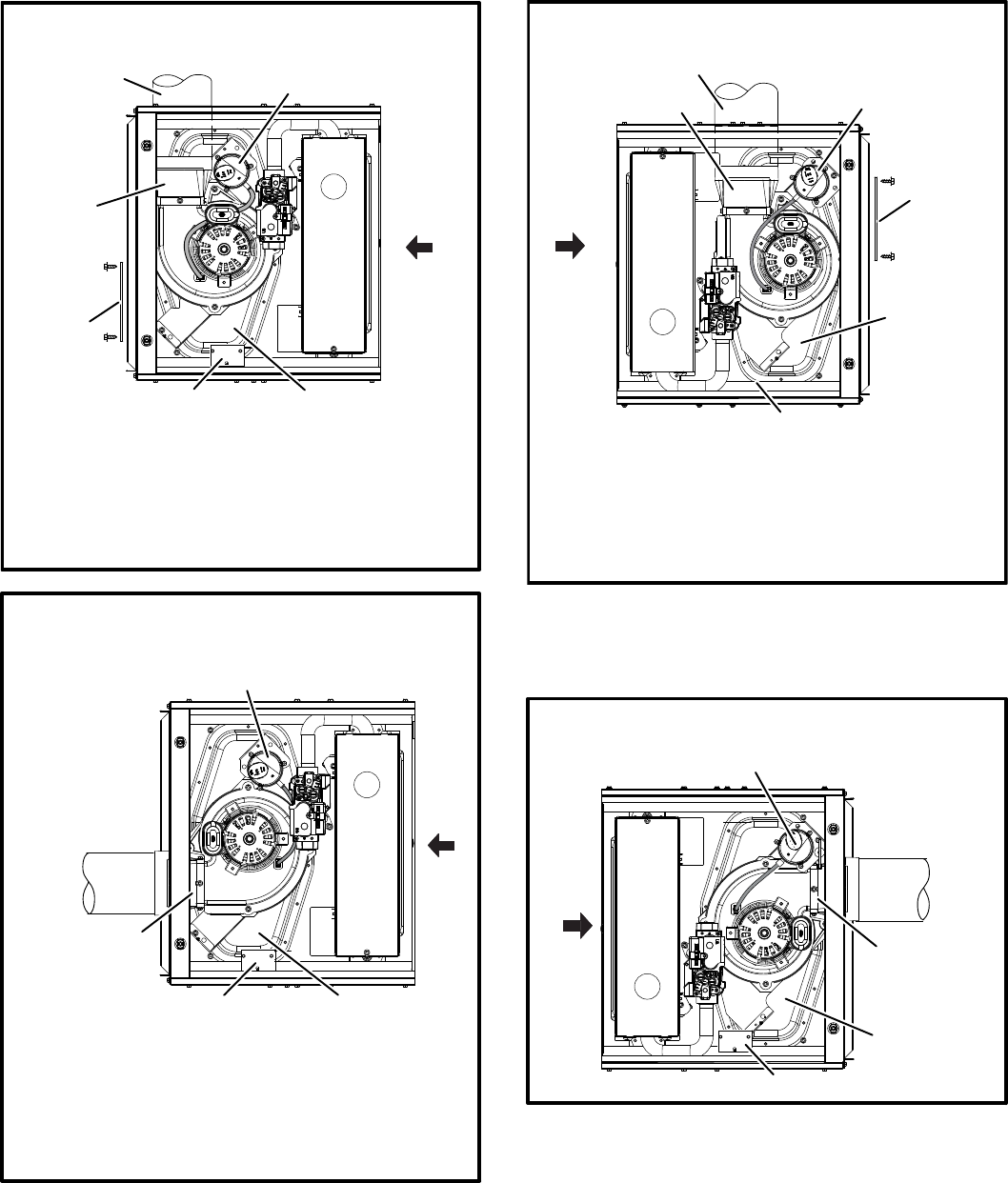
FIGURE 18
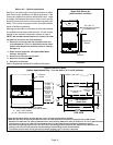
HORIZONTAL LEFT POSITION
Top Vent Discharge
S Disconnect pressure switch hose from barbed fitting on the pres-
sure switch assembly. Remove pressure switch assembly (1
screw) and cut wire tie to free pressure switch wires. Re−install
pressure switch on the other side of orifice plate and re−connect
pressure switch hose.
S Re−secure pressure switch wires by either pulling excess wires
through the blower compartment and securing with supplied wire
tie or coil excess wire and secure to the gas manifold.
pressure switch
vent pipe
flue
transition
cover plate
make−up box
collector box
FLOW
AIR
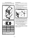
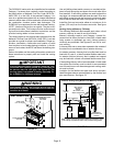
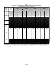
FIGURE 19
make−up box
collector box
flue transition
pressure switch
HORIZONTAL LEFT POSITION
Side Vent Discharge
S Disconnect pressure switch hose from barbed fitting on the
pressure switch assembly. Remove pressure switch assembly
(1 screw) and cut wire tie to free pressure switch wires. Re−
install pressure switch on the other side of orifice plate and re−
connect pressure switch hose.
S Re−secure pressure switch wires by either pulling excess wires
through the blower compartment and securing with supplied
wire tie, or coil excess wire and secure to the gas manifold.
FLOW
AIR
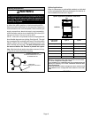
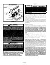
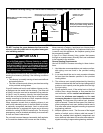
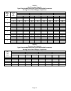
HORIZONTAL RIGHT POSITION
Top Vent Discharge
FIGURE 20
S Gas supply piping must be brought into the unit from the bottom
in order to accommodate the flue pipe.
S Remove make−up box assembly (2 screws) and cut wire tie to
free make−up box wires. Re−install make−up box on other side
of cabinet.
S Re−secure make−up box wires by either pulling excess wires
through the blower compartment and securing with supplied
wire tie, or coil excess wire and secure to the gas manifold.
FLOW
AIR
flue transition
vent pipe
pressure switch
cover plate
make−up box
collector box
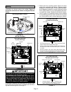
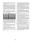
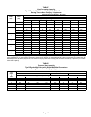
HORIZONTAL RIGHT POSITION
Side Vent Discharge
FIGURE 21
FLOW
AIR
pressure switch
flue transition
collector box
make up box