


Page 9
Downflow Installation
Downflow unit installs in three ways: on non−combustible
flooring, on combustible flooring using a downflow com-
bustible flooring base, or on a reverse−flow cooling cabinet.
Do not drag the unit across the floor.
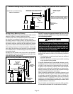
Installation on Non−Combustible Flooring (Figure 6)
1 − Cut floor opening keeping in mind clearances listed on
unit rating plate. Also keep in mind gas supply connec-
tions, electrical supply, flue and air intake connections
and sufficient installation and servicing clearances.
See table 1 for correct floor opening size.
2 − Flange warm air plenum and lower the plenum into the
opening.
3 − Set the unit over the plenum and seal the plenum to
the unit.
4 − Ensure that the seal is adequate.
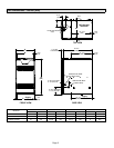
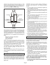
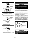
FIGURE 6
SL280DFV UNIT
SUPPLY AIR
PLENUM
OPENING
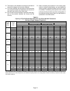
TABLE 1
NON−COMBUSTIBLE FLOOR OPENING SIZE
Cabinet Width
Front to Rear Side to Side
in. mm in. mm
A (14.5") 19−3/4 502 13−1/4 337
B (17.5") 19−3/4 502 16−1/4 413
C (21") 19−3/4 502 19−3/4 502
NOTE − Door opening dimensions listed are 1/4 inch (6 mm) larger than
the unit opening. See unit dimensions on page 2.
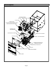
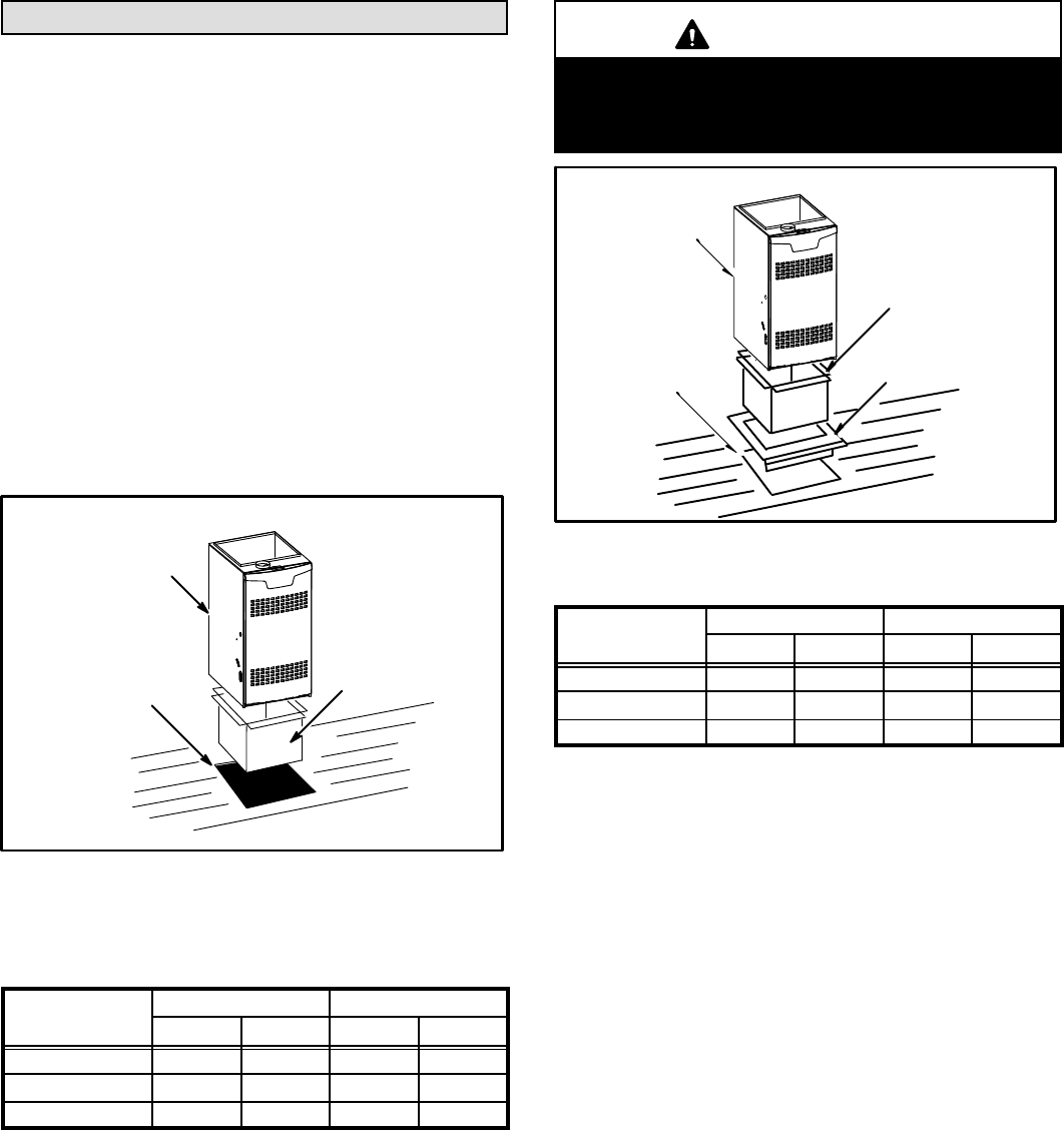
Installation on Combustible Flooring (Figure 7)
1 − When unit is installed on a combustible floor, a down-
flow combustible flooring base must be installed be-
tween the furnace and the floor. The base must be or-
dered separately.
See table 2 for opening size to cut in floor.
CAUTION
The furnace and downflow combustible flooring
base shall not be installed directly on carpeting, tile,
or other combustible material other than wood floor-
ing.
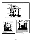
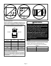
SL280DFV UNIT
SUPPLY AIR PLENUM
DOWNFLOW
COMBUSTIBLE
FLOORING BASE
PROPERLY
SIZED FLOOR
OPENING
FIGURE 7
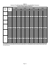
TABLE 2
COMBUSTIBLE FLOOR OPENING SIZE
Cabinet Width
Front to Rear Side to Side
in. mm in. mm
A (14.5")
22 559 15−3/4 400
B (17.5")
22 559 18−3/4 476
C (21")
22 559 22−3/4 578
NOTE − Floor opening dimensions listed are 1/4 inch (6 mm) larger than
unit opening. See unit dimensions on page 2.
2 − After opening is cut, set combustible flooring base into
opening.
3 − Check sealing strips on combustible flooring base to
make sure they are properly glued and positioned.
4 − Lower supply air plenum into downflow combustible
flooring base until plenum flanges seal against the
strips.
NOTE − Be careful not to damage sealing strips. Check
for a tight seal.
5 − Set the furnace over the plenum.
6 − Ensure that the seal between the furnace and plenum
is adequate.
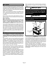
Installation on Cooling Cabinet (Figure 8)
1 − Refer to reverse−flow coil installation instructions for
correctly sized opening in floor and installation of cabi-
net.
NOTE − Downflow combustible flooring kit is not used
2 − When cooling cabinet is in place, set and secure the
furnace according to the instructions that are provided
with the cooling coil. Secure the furnace to the cabinet.
3 − Seal the cabinet and check for air leaks.