


Page 40
12− If the appliance will not operate, follow the instructions
Turning Off Gas to Unit" and call your service techni-
cian or gas supplier.
Turning Off Gas to Unit
1 − Set the thermostat to the lowest setting.
2 − Turn off all electrical power to the unit if service is to be
performed.
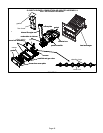
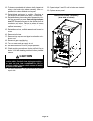
3 − Remove the upper access panel.
4 − Move switch on gas valve to OF. Do not force. See fig-
ure 26 or 27.
5 − Replace the upper access panel.
Failure To Operate
If the unit fails to operate, check the following:
1 − Is the thermostat calling for heat?
2 − Are access panels securely in place?
3 − Is the main disconnect switch closed?
4 − Is there a blown fuse or tripped circuit breaker?
5 − Is the filter dirty or plugged? Dirty or plugged filters will
cause the limit control to shut the unit off.
6 − Is gas turned on at the meter?
7 − Is the manual main shut-off valve open?
8 − Is the internal manual shut-off valve open?
9 − Is the unit ignition system in lock out? If the unit locks out
again, call the service technician to inspect the unit for
blockages.
10 −Is pressure switch closed? Obstructed flue will cause
unit to shut off at pressure switch. Check flue and outlet
for blockages.
11 −Is the rollout switch tripped? If the switch is tripped call
the service technician to inspect the unit.
Gas Pressure Adjustment
Gas Flow (Approximate)
Furnace should operate at least 5 minutes before check-
ing gas flow. Determine time in seconds for two revolu-
tions of gas through the meter. (Two revolutions assures a
more accurate time.) Divide by two and compare to time
in table 22 below. If manifold pressure matches table 24
and rate is incorrect, check gas orifices for proper size and
restriction. Remove temporary gas meter if installed.
NOTE − Shut unit off and remove manometer as soon as an
accurate reading has been obtained. Take care to replace
pressure tap plug.
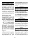
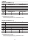
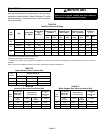
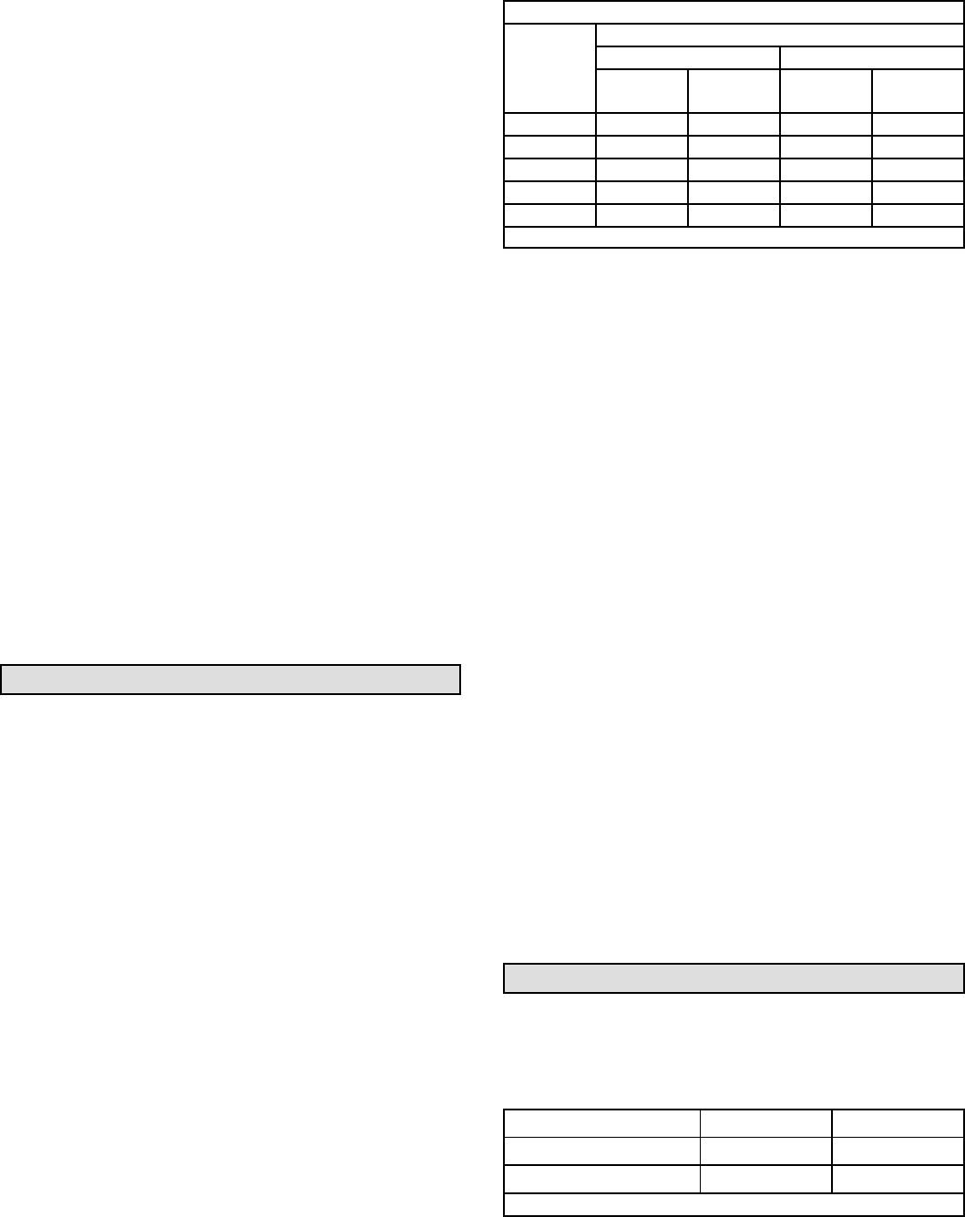
TABLE 22
GAS METER CLOCKING CHART
SL280
Unit
Seconds for One Revolution
Natural LP
1 cu ft
Dial
2 cu ft
Dial
1 cu ft
Dial
2 cu ft
DIAL
−045 80 160 200 400
−70 55 110 136 272
−90 41 82 102 204
−110 33 66 82 164
−135 27 54 68 136
Natural−1000 btu/cu ft LP−2500 btu/cu ft
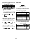
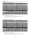
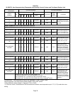
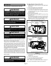
Supply Line Pressure
White Rodgers Gas Valve
An inlet post located on the gas valve provides access to
the supply pressure. See figure 27. Back out the 3/32 hex
screw one turn, connect a piece of 5/16 tubing and connect
to a manometer to measure supply pressure. See table 24
for supply line pressure.
Honeywell Gas Valve
A threaded plug on the inlet side of the gas valve provides
access to the supply pressure tap. Remove the threaded
plug, install a field−provided barbed fitting and connect a
manometer to measure supply pressure. See table 24 for
supply line pressure. Replace the threaded plug after mea-
surements have been taken.
Manifold Pressure
NOTE − Pressure test adapter kit (10L34) is available from
Lennox to facilitate manifold pressure measurement.
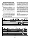
1 − Connect test gauge to manifold pressure post (figure
26) or tap (figure 27) on gas valve.
2 − Ignite unit on high fire and let run for 5 minutes to allow
for steady state conditions.
3 − After allowing unit to stabilize for 5 minutes, record
manifold pressure and compare to value given in table
24.
4 − If necessary, make adjustments. Figures 26 and 27
show location of high fire adjustment screw.
5 − If an adjustment is made on high fire, re−check man-
ifold pressure on low fire. Do not adjust low fire man-
ifold pressure. If low fire manifold pressure is more
than 1/2" above or below value specified in table 24,
replace valve.
Proper Combustion
Furnace should operate minimum 15 minutes with correct
manifold pressure and gas flow rate before checking com-
bustion. Table 23 shows acceptable combustion for ALL
SL280DFV models.
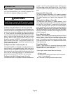
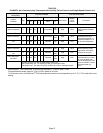
TABLE 23
Firing Rate
CO
2
%
For
Nat
CO
2
%
For
L.P.
High Fire 6.0 − 7.4 6.9 − 8.4
Low Fire 4.8 − 6.0 5.7 − 7.0
The carbon monoxide reading should not exceed 50 ppm.