


Page 23
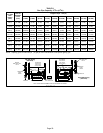
Generator Use − Voltage Requirements
The following requirements must be kept in mind when
specifying a generator for use with this equipment:
S The furnace requires 120 volts (Range: 102 volts to
132 volts)
S The furnace operates at 60 Hz +
5% (Range: 57 Hz to
63 Hz)
S The furnace integrated control requires both correct
polarity and proper ground. Both polarity and proper
grounding should be checked before attempting to op-
erate the furnace on either permanent or temporary
power
S Generator should have a wave form distortion of less
than 5% THD (total harmonic distortion)
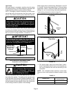
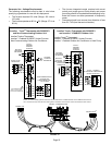
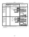
FIGURE 21
icomfort Touch
®
Thermostat with SL280DFV
and Non−Communicating Outdoor Unit
icomfortt−
ENABLED
SL280DFV
FURNACE
icomfort Touch®
THERMOSTAT
NON−COMMUNICATING
OUTDOOR AIR
CONDITIONING UNIT −
1 OR 2 STAGE
icomfort Touch
®
Thermostat
icomfortt−Enabled SL280DFV Indoor Furnace
Non−Communicating Outdoor Air Conditioner
OPTIONAL
OUTDOOR
AIR SENSOR
OPTIONAL
DISCHARGE
AIR SENSOR
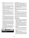
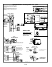
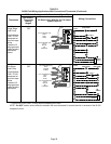
icomfort Touch
®
Thermostat with SL280DFV
and icomfortt−ENABLED Outdoor Unit
icomfort Touch
®
Thermostat
icomfortt−Enabled SL280DFV Indoor Furnace
icomfortt−Enabled Outdoor Air Conditioner or Heat Pump
icomfortt−
ENABLED
SL280DFV
FURNACE
icomfortt− ENABLED
OUTDOOR AIR CONDITIONING
OR HEAT PUMP UNIT
OPTIONAL
OUTDOOR
AIR SENSOR
OPTIONAL
DISCHARGE
AIR SENSOR
CLIP ON−BOARD LINK
W915 (Y1 TO Y2) FOR
TWO−STAGE OPERATION
icomfort Touch®
THERMOSTAT
icomfortt Integrated Control
icomfort Touch
®
Outdoor Unit
NOTE − On communicating systems, extra wires must terminate on the "C" RSBus terminal. Use an additional wire and come
off "C" terminal and wire nut all the extra wires together. Termination on the outdoor control must match the indoor control.