


Page 10
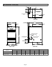
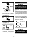
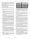
SL280DFV UNIT
COOLING COIL
PLENUM
FIGURE 8
PROPERLY
SIZED FLOOR
OPENING
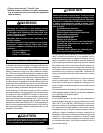
Return Air Opening −− Downflow Units
The following steps should be taken when installing ple-
num:
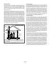
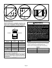
1 − Bottom edge of plenum should be flanged with a
hemmed edge (See figure 9).
SECURE FROM
OUTSIDE CABINET
HEMMED EDGE
PLENUM
SEALING STRIP
(Field Provided)
CABINET SIDE PANEL
Side View
FIGURE 9
2 − Sealing strip should be used.
3 − In all cases, plenum should be secured to top flanges
of furnace with sheet metal screws.
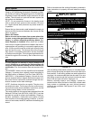
SECURE FROM IN-
SIDE CABINET
HEMMED EDGE
FIBERGLASS
SEALING STRIP
(Field Provided)
CABINET SIDE
PANEL
PLENUM
Side View
FIGURE 10
4 − In closet installations, it may be impossible to install
sheet metal screws from the outside. In this case,
make plenum with a removable front and install
screws from the inside (See figure 10).
5 − Make certain that an adequate seal is made.
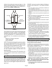
Setting Equipment
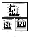
WARNING
Do not install the furnace on its front, back or in the
horizontal position. See figure 12. Do not connect the
return air ducts to the back of the furnace. Doing so
will adversely affect the operation of the safety con-
trol devices, which could result in personal injury or
death.
Install the SL280DFV gas furnace as shipped in the
downflow position only. Do not install the furnace hori-
zontally.
Select a location that allows for the required clearances
that are listed on the unit nameplate. Also consider gas
supply connections, electrical supply, vent connection,
and installation and service clearances [24 inches (610
mm) at unit front]. The unit must be level.
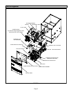
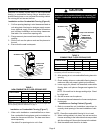
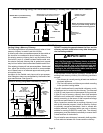
NOTE − Units with 1/2 hp blower motors are equipped with
three flexible legs and one rigid leg. See figure 11. The rigid
leg is equipped with a shipping bolt and a flat white plastic
washer (rather than the rubber mounting grommet used
with a flexible mounting leg). The bolt and washer must
be removed before the furnace is placed into opera-
tion. After the bolt and washer have been removed, the rig-
id leg will not touch the blower housing.
FIGURE 11
RIGID LEG
remove shipping bolt and washer
SL280DFV07036A WITH 1/2 HP
BLOWER MOTOR
WARNING
The blower access panel must be securely in place
when the blower and burners are operating. Gas
fumes, which could contain carbon monoxide, can
be drawn into living space resulting in personal inju-
ry or death.