


Page 11
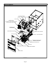
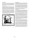
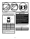
FIGURE 12
Front
Back
Horizontal
Downflow Application
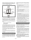
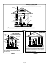
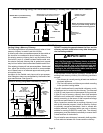
Allow for clearances to combustible materials as indi-
cated on the unit nameplate. Minimum clearances for
closet or alcove installations are shown in figure 13.
Downflow Application Installation Clearances
Top
Bottom
Left Side
Right Side
Type of Vent
Connector
Type C Type B1
Top 1 in. (25 mm) 1 in. (25 mm)
*Front 2−1/4 in. (57 mm)** 2−1/4in. (57 mm)
Back 0 0
Sides 0† 0
Vent 6 in. (152 mm) 1 in. (25 mm)
Floor NC†† NC††
*Front clearance in alcove installation must be 24 in. (610 mm).
Maintain a minimum of 24 in. (610 mm) for front service access.
** 3−1/4 in. if single wall vent pipe is used.
†Left side requires 3 in. if a single wall vent is used on 14 −1/2 in. cab-
inets, or 2 in. if a single wall vent is used on 17 − 1/2 in. cabinets.
††The furnace may be installed on a combustible wood floor if an
optional additive base is installed between the furnace and the
combustible floor.
FIGURE 13
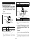
WARNING
Improper installation of the furnace can result in per-
sonal injury or death. Combustion and flue products
must never be allowed to enter the return air system
or the living space. Use screws and joint tape to seal
the return air system to the furnace.
In platform installations with bottom return air, the
furnace should be sealed airtight to the return air ple-
num. A door must never be used as a portion of the
return air duct system. The base must provide a
stable support and an airtight seal to the furnace. Al-
low absolutely no sagging, cracks, gaps, etc.
The return and supply air duct systems must never
be connected to or from other heating devices such
as a fireplace or stove, etc. Fire, explosion, carbon
monoxide poisoning, personal injury and/or proper-
ty damage could result.
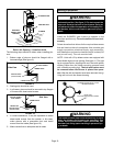
Filters
This unit is not equipped with a filter or rack. A field−pro-
vided high−velocity filter is required for the unit to operate
properly. Table 3 lists recommended filter sizes.
A filter must be in place any time the unit is operating.
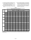
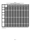
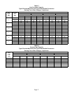
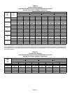
TABLE 3
Cabinet Width
Return Air Filter Size (inches)
A (14−1/2") 14 x 25 x 1 (1)
B (17−1/2") 16 x 25 x 1 (1)
C (21") 20 x 25 x 1 (1)