


Page 21
Leak Check
After gas piping is completed, carefully check all piping
connections (factory− and field−installed) for gas leaks. Use
a leak detecting solution or other preferred means.
NOTE − If emergency shutoff is necessary, shut off the main
manual gas valve and disconnect the main power to the
furnace. The installer should properly label these devices.
CAUTION
Some soaps used for leak detection are corrosive to
certain metals. Carefully rinse piping thoroughly af-
ter leak test has been completed. Do not use
matches, candles, flame or other sources of ignition
to check for gas leaks.
The furnace must be isolated from the gas supply system
by closing its individual manual shut-off valve during any
pressure testing of the gas supply system at pressures less
than or equal to 1/2 psig (3.48 kPa, 14 inches w.c.).
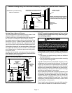
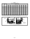
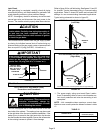
IMPORTANT
When testing pressure of gas lines, gas valve must
be disconnected and isolated. See figure 18. Gas
valves can be damaged if subjected to pressures
greater than 1/2 psig (3.48 kPa, 14 inches w.c.).
MANUAL MAIN
SHUT−OFF VALVE
WILL NOT HOLD
NORMAL TEST
PRESSURE
CAP
ISOLATE
GAS VALVE
FURNACE
FIGURE 18
1/8 NPT PLUG
Electrical
ELECTROSTATIC DISCHARGE (ESD)
Precautions and Procedures
CAUTION
Electrostatic discharge can affect elec-
tronic components. Take precautions to
neutralize electrostatic charge by
touching your hand and tools to metal
prior to handling the control.
The unit is equipped with a field make−up box on the left
hand side of the cabinet. The make−up box may be moved
to the right side of the furnace to facilitate installation. If the
make−up box is moved to the right hand side, clip the wire
ties that bundle the wires together. Secure the excess wire
to the existing harness to protect it from damage.
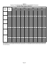
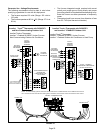
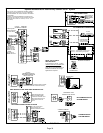
Refer to figure 24 for unit field wiring. See figures 21 and 22
for icomfort Touch
®
thermostat wiring in communicating
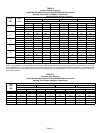
applications. Table 13 shows DIP switch and on−board link
settings for non−communicating thermostat applications.
Typical wiring schematic is shown in figure 23.
FIGURE 19
INTERIOR MAKE−UP BOX INSTALLATION
(Left Side)
MAKE−UP
BOX
INTERIOR MAKE−UP BOX INSTALLATION
(Right Side)
FIGURE 20
MAKE−UP
BOX
Cut the two wire ties to extend power wires for right side only
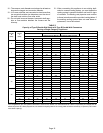
1 − The power supply wiring must meet Class I restric-
tions. Protected by either a fuse or circuit breaker, se-
lect circuit protection and wire size according to unit
nameplate.
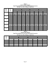
NOTE − Unit nameplate states maximum current draw.
Maximum over−current protection allowed is shown in table
12.
TABLE 12
SL280DF Model
Maximum Over−Current
Protection (Amps)
070V36A 15
090V48B, 090V60C, 110V60C 20