


Page 9
CBWMV SERIES
Electrostatic Discharge (ESD) - Precautions
And Procedures
CAUTION
Electrostatic discharge can affect electronic com-
ponents. Take precautions during air handler instal-
lation and service to protect the air handler’s elec-
tronic controls. Precautions will help to avoid con-
trol exposure to electrostatic discharge by putting
the air handler, the control and the technician at the
same electrostatic potential. Neutralize electrostatic
charge by touching hand and all tools on an un-
painted unit surface, such as the blower deck, be-
fore performing any service procedure.
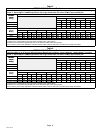
Refer to table 3 for field wiring.
1. Refer to the CBWMV unit’s nameplate for minimum
circuit ampacity and maximum overcurrent protection
size.
2. Install a separate disconnect switch (protected by ei-
ther fuse or circuit breaker) near the air handler so that
power can be turned off for servicing.
3. Complete the wiring connections to the equipment.
Use the provided unit wiring diagram and the field wir-
ing diagrams shown in table 3. Use 18−gauge wire or
larger that is suitable for Class II rating for thermostat
connections.
4. Electrically ground the unit according to local codes or,
in the absence of local codes, according to the current
National Electric Code (ANSI/NFPA No. 70) for the
USA and current Canadian Electric Code part 1 (CSA
standard C22.1) for Canada. A green ground wire is
provided in the field make−up box.
5. Install the room thermostat according to the instruc-
tions provided with the thermostat. See table 3 for field
wiring connections in varying applications. If the air
handler is being matched with a heat pump, refer to the
FuelMaster21
®
installation instruction.
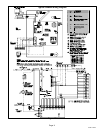
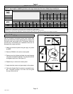
Removeable Jumpers
Removeable Jumper DS to Y1ĊThe factory−installed
wire jumper that connects terminals DS and Y1 on the TB1
terminal strip in the control box must be removed when the
air handler is installed in a system supporting dehumidifi-
cation using a SignatureStat
t
thermostat (e.g., Humidi-
trol
®
Enhanced Dehumidification Accessory or Harmony
t
zone controls).
Removeable Jumper R to OĊThe factory−installed wire
jumper that connects TB7 (24V) terminal R to TB1 termi-
nal O must be removed when the air handler is installed in
applications which include a heat pump unit and the Fuel-
Master21
®
control board. If the jumper is left intact, termi-
nal O will remain energized, eliminating the heat mode in
the heat pump.
Removeable Jumper Y1 to Y2ĊThe factory−installed
wire jumper that connects Y1 and Y2 on the TB1 terminal
strip must be removed if two−stage cooling is used. If the
jumper is not removed the outdoor unit will only operate in
second−stage cooling.
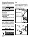
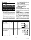
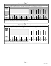
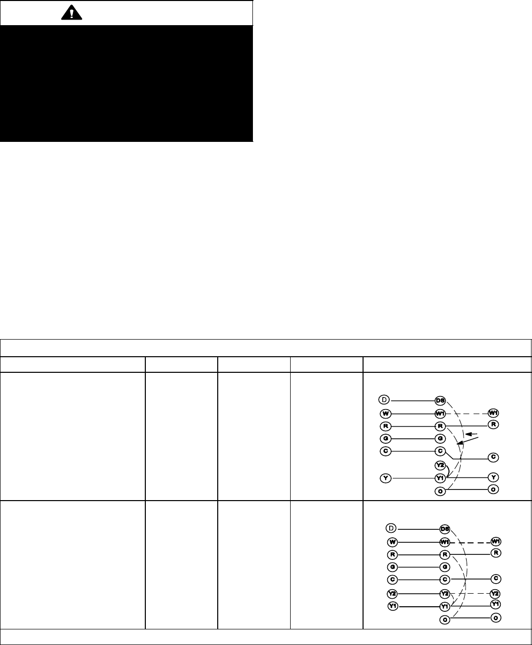
Table 3
Field Wiring Application Jumper Settings (See figure 12)
Thermostat (Application) TB1 Y1 to Y2 TB1 DS to Y1 TB1 R to O Wiring Connections
1 Heat / 1 Cool with
SignatureStatt Thermostat
[Single-Stage Heat Pump]
Yes No
(Remove)
No
(Remove)
SignatureStatt CBWMV
TERMINALS
OUTDOOR
UNIT
JUMPERS
REMOVED
2 Heat / 2 Cool with
SignatureStatt Thermostat
[Two-Stage Heat Pump (Refer
to FM21 Instructions)]
No
(Remove)
No
(Remove)
No
(Remove)
CBWMV
TERMINALS
OUTDOOR
UNIT
SignatureStatt
ALL JUMPERS
REMOVED
O" terminal used only with heat pumps.