


Page 12
505047 09/06
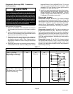
Freezestat Operation
IMPORTANT
Use of the freezestat feature is required in all instal-
lations using CBWMV units.
The CBWMV unit is equipped with a field-wired freezestat.
The freezestat protects the CBWMV system from freezing
temperatures when the unit is installed in unconditioned
areas.
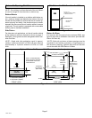
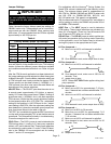
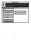
The factory-provided freezestat must energize the circula-
tor when water temperatures fall below 45ºF. Freezestat
wiring is shown in figure 13.
Figure 13
Freezestat Field Wiring
BDC3 Variable Blower Control Board
CBWMV units are equipped with a variable speed motor
that is capable of maintaining a specified CFM throughout
the external static range. A particular CFM can be obtained
by positioning jumpers (COOL, HEAT, and ADJUST) on
the BDC3 control board. The COOL and HEAT jumpers
are labeled 1, 2, 3, and 4. Each of the numbers corre-
sponds with an air volume (CFM) setting. The ADJUST
jumper is labeled TEST, −, +, and NORM. The + and − pin
settings are used to add or subtract a percentage of the
CFM selected. The TEST jumper is used to operate the
motor in the test mode. The DELAY jumper controls ramp-
ing profiles.
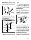
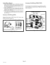
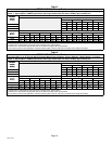
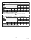
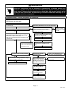
Figure 14 shows the BDC3 control board. Use tables 5
through 9 to determine the correct air volume for heat and
cool speed taps.
Diagnostic LEDs located on the BDC3 control board are
provided to aid in identifying the unit’s mode of operation.
Certain scenarios will arise depending on the jumper posi-
tions. Read through the jumper settings sections before
adjusting blower speed. Refer to figure 14 for identification.
Continuous Low Blower Option
Refer to the blower speed chart located on the CBWMV
unit wiring diagram for factory set cooling, heating and low
(continuous) blower speeds. Systems using a cooling ther-
mostat subbase may operate continuous blower (factory-
set to operate at 38% of second-stage cooling speed)
through the FAN−ON switch of the thermostat. For continu-
ous low blower with a system without a cooling subbase, a
fan switching subbase may be used.
Heating or cooling demand will cause blower to go to heat
or cool speed.
Blower Speed Adjustments
Diagnostic LEDs
RUN LED Ċ Indicates a demand for blower operation in
either the heating mode or continuous fan−only mode.
RUN LED will not illuminate during a cooling demand.
CFM LED Ċ Indicates the CFM at which the unit is operat-
ing. The light flashes once for approximately every 100
CFM. For example, if the unit is operating at 1000 CFM,
CFM LED will flash 10 times. If the CFM is 1150, CFM LED
will flash 11 full times plus one fast or half flash.
At times the light may appear to flicker or glow. This takes
place when the control is communicating with the motor
between cycles. This is normal operation.
The appropriate speed according to application and CFM
need is selected by moving jumper pins.
Figure 14
BDC3 Variable Speed Control Board
JP1
15 PIN PLUG
(BOARD TO
MOTOR)
ACCESSORY
RELAY CON-
TACTS
(DRIVES OP-
TIONAL
ACCESSORY
RELAY)
OPERATIONAL
SELECTOR
PINS
(AFFECTS
BOTH
HEATING AND
COOLING
MODES)
DIAGNOSTIC
LEDS
HEATING SPEED
SELECTOR PINS
COOLING SPEED
SELECTOR PINS
FAN DELAY
SELECTOR PINS