


Page 18
505047 09/06
WARNING
WARNING TO SERVICE PERSONS! Electric shock hazard. When electrical power to the internal
control box components must be available for troubleshooting, a common practice is to
construct a by−pass" of the door interlock switch. When such a by−pass is in place, a potential
shock hazard is present which can cause injury or death. Make sure any door interlock switch
by−pass has been removed after troubleshooting is complete and BEFORE attempting any re-
pairs to the control box components!
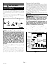
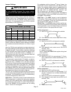
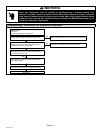
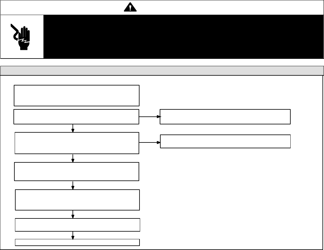
Troubleshooting: Continuous Fan Sequence of Operation
Thermostat (S1) Calls for Continuous Fan, G−Only
Blower Operates at the Continuous Fan Speed
Selected by COOL Jumper and ADJUST Jumper
Positions on the BDC3 Control (A52)
RUN Light on BDC3 Control (A52) illuminates to Indi-
cate a Continuous Fan Call
Blower Off
CFM Light on A52 Indicates Blower CFM Selection
with 100CFM / Blink
Thermostat (S1) Continuous Fan Demand Satisfied
Check for 24 Volts Between ’G’ and C at A15 Terminal Strip
Check for 24 Volts Between Pins 3 and 15 on J49
CONDITIONS:
Power On
Normal Operation LED: Steady Flash
NO
YES
YES
YES
NO
YES
YES