


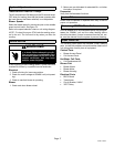
Page 16
505047 09/06
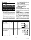
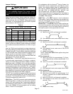
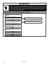
Table 9
CBWMV−60C−120 Blower Performance
0 through 0.80 in. w.g. (0 Through 200 Pa) External Static Pressure Range ; Factory Settings: Heating Speed − 4, Cooling
Speed − 4, Speed Adjust − NORM; Applications with single sided inlets will reduce CFM by approximately 5%.
ADJUST"
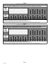
BDC3 Jumper Speed Positions
ADJUST"
Jumper
1st Stage COOL" Speed
J
umper
Sett
in
g
1 2 3 4
Setting
cfm L/s cfm L/s cfm L/s cfm L/s
+ 1100 520 1250 590 1400 660 1560 735
NORM 990 465 1130 535 1260 595 1400 660
Ċ 930 440 1020 480 1130 535 1260 595
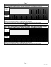
ADJUST"
HEAT" Speed 2nd Stage COOL" Speed
ADJUST
Jumper
S
1 2 3 4 1 2 3 4
p
Setting
cfm L/s cfm L/s cfm L/s cfm L/s cfm L/s cfm L/s cfm L/s cfm L/s
+ 1510 715 1720 810 1900 895 2120 1000 1570 740 1800 850 2000 945 2200 1040
NORM 1380 650 1560 135 1740 820 1920 905 1410 665 1620 765 1820 860 2020 955
Ċ 1240 585 1380 650 1540 725 1720 810 1260 595 1440 680 1620 765 1810 855
The effect of static pressure and filter resistance is included in air volumes shown.
1st stage COOL is approximately 70% of the same 2nd stage COOL speed position.
Continuous Fan Only speed is approximately 38% of the same 2nd stage COOL speed position.
Lennox Harmony zone control applications − Minimum blower speed is 600 cfm. Max cfm is the same as 2nd stage cool position.
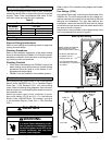
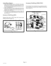
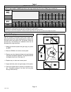
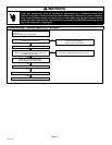
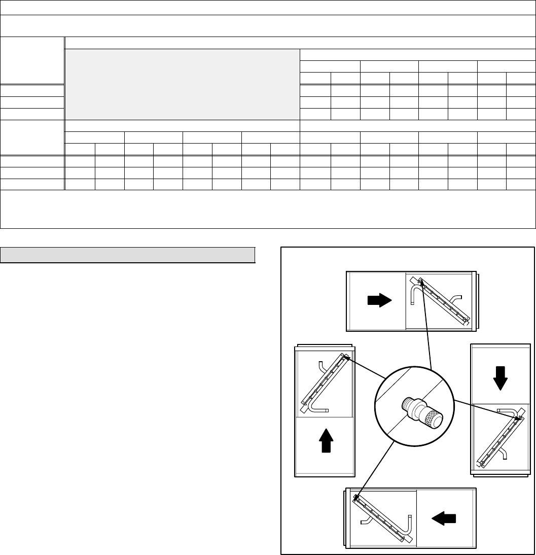
Initial Air Purging
After all plumbing connections have been made, leak
tested and flushed, the water heating device is ready to be
filled with water and purged of air. Air bleeder valves are
provided as a convenience for installations that are not
equipped with purge manifolds.
1. Make sure electrical power and gas supply to system
are OFF.
2. Remove CBWMV coil section access panel.
3. Remove cap from highest air bleed valve and depress
valve stem until water is released. This may be done with
a refrigerant style hose. See figure 15.
4. Replace cap on valve and access panel.
5. Apply electrical power and gas supply to the system.
6. Follow the System Start−Up section to operate the sys-
tem. Complete purging of air after unit has gone
through initial start−up.
Figure 15
Air Bleed Valve Location
VALVE
SHOWN
WITH CAP ON