


Page 7
CBWMV SERIES
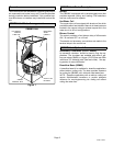
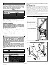
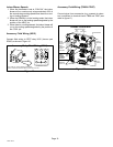
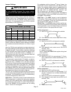
Removing the Bottom Panel (bottom return or return
air base configurations)ĊRemove the two screws that
secure the bottom cap to the air handler. Pivot the bottom
cap down to release the bottom panel. Once the bottom
panel has been removed, reinstall the bottom cap. See fig-
ure 5.
Removing the Bottom Panel
Figure 5
SCREW
BOTTOM PANEL
BOTTOM CAP
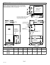
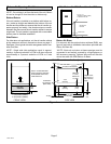
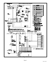
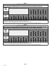
Leveling an Upflow UnitĊWhen the side return air inlets
are used in an upflow application, it may be necessary to
install leveling bolts on the bottom of the air handler. Use
field−supplied corrosion−resistant 5/16 inch machine bolts
(4) and nuts (8). See figure 6.
NOTE − Maximum leveling bolt length is 1−1/2 inches.
Figure 6
Leveling Bolt Installation
1−3/4 (44)
3/8 (10)
3/8 (10)
3/8 (10)
3/8 (10)
LEVELING BOLT
LOCATIONS
LEVELING BOLT
LOCATIONS
inches (mm)
AIR HANDLER FRONT
AIR
HANDLER
BOTTOM
1−3/4 (44)
1−3/4 (44)
1−3/4 (44)
1. Lay the air handler on its back and drill a 5/16 inch di-
ameter hole in each corner of the air handler’s bottom.
See figure 6 for the correct location of the holes. Drill
through the bottom panel and the bottom flange of the
cabinet.
2. Install one bolt and two nuts into each hole. Screw the
first nut onto a bolt and then insert the bolt into a hole.
A flat washer may be added between the nut and the
bottom of the unit.
3. Screw another nut onto the bolt on the inside of the air
handler base. A flat washer may be added between
the nut and the bottom of the unit.
4. Adjust the outside nut to the appropriate height and
tighten the inside nut to secure the arrangement.
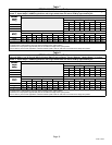
Horizontal Applications
The CBWMV air handler can be installed in horizontal ap-
plications. Refer to Engineering Handbook for additional in-
formation. Allow for clearances to combustible materials as
indicated on the unit nameplate.
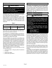
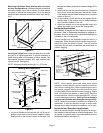
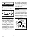
This air handler may be installed in either an attic or a
crawlspace. Either suspend the air handler from roof raf-
ters or floor joists, as shown in figure 7. The unit must be
supported at both ends and beneath the blower deck to
prevent sagging.
Unit Suspended in Attic or Crawlspace
ALLOW
SUFFICIENT
CLEARANCE
BETWEEN ROD
AND UNIT TO
REMOVE
ACCESS PANEL.
Figure 7
1/4 IN.
RODS
ANGLE IRON
U−CHANNELS
DRAIN
PAN
NOTE − Heavy−gauge, perforated sheet metal straps
(plumbers’ straps) may be used to suspend the unit from
roof rafters or ceiling joists. When suspending the unit in
this manner, support must be provided for both the ends
and the middle of the air handler to prevent sagging. Straps
must not interfere with plenum or water piping. Securing
screws should be 1/2 inch from the top edge and 1−1/2 inch
from the side edge in all cases. Cooling coils and supply
and return air plenums must be supported separately.
NOTE − When the air handler is installed on a platform in a
crawlspace, it must be elevated enough to avoid water
damage and to allow the optional evaporator coil to drain.
Horizontal and Downflow Applications
Return air can be brought in through the end of an air han-
dler installed in the horizontal or downflow application. The
air handler is equipped with a removable bottom panel to
facilitate installation (see figure 5).