


Page 8
505047 09/06
Filter Assembly & Filters
This unit is not equipped with a filter or rack. A field−pro-
vided high−velocity filter is required for the unit to operate
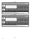
properly. Table 2 lists recommended filter sizes. A filter
must be in place any time the unit is operating.
Table 2
Recommended Filter Sizes
Air Handler
Filter Size
Air
Handler
Cabinet Size
Side Return Bottom Return
17−1/2" 16 X 25 X 1 (1) 16 X 25 X 1 (1)
21" 16 X 25 X 1 (1) 20 X 25 X 1 (1)
Plumbing
Pipe and Fitting Specifications
Refer to local building and plumbing codes for approved
copper pipe and fittings.
Plumbing Procedures
Refer to the installation instructions of the water heating
device to be used with the CBWMV unit. Follow the recom-
mendations outlined in that instruction as well as govern-
ing plumbing codes and practices.
Plumbing Checklist
S Flush water lines between the CBWMV unit and the
water heating device before start−up. Normal flushing
procedures should be used to rid the system of con-
taminants and foreign debris.
S CBWMV units are installed in non-potable systems.
Electrical
Wiring and grounding must conform to the current National
Electric Code ANSI/NFPA No. 70, or Canadian Electric
Code Part I, CSA Standard C22.1, and local building
codes. Refer to following wiring diagrams. See unit name-
plate for minimum circuit ampacity and maximum overcur-
rent protection size.
Select the proper supply circuit conductors in accor-
dance with tables 310−16 and 310−17 in the National
Electric Code, ANSI/NFPA No. 70 or tables 1 through 4
in the Canadian Electric Code, Part I, CSA Standard
C22.1.
CAUTION
USE COPPER CONDUCTORS ONLY.
WARNING
Electric shock hazard. Can cause inju-
ry or death. Before attempting to per-
form any service or maintenance, turn
the electrical power to unit OFF at dis-
connect switch(es). Unit may have
multiple power supplies.
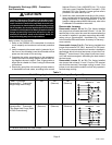
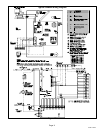
Refer to figure 12 for schematic wiring diagram and trouble-
shooting.
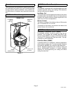
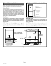
Line Voltage (120V)
Line voltage field supply conductors are terminated at the
CBWMV unit. The unit is shipped with the line voltage con-
nections secured to the lower left coil manifold for left side
make−up box installations. For right side make−up box
installations, remove the wire tie that holds the line voltage
connections and pull excess wires into blower deck/control
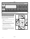
box area as shown in figure 8.
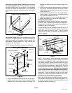
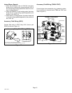
Install make−up box (provided for line voltage wiring in the
unit’s bag assembly) as shown in figure 9.
WIRES SHOWN AS SHIPPED,
ROUTED FOR LEFT SIDE
MAKE−UP BOX INSTALLATION
FOR RIGHT SIDE MAKE−UP
BOX INSTALLATION Ċ
REMOVE WIRE TIE,
PULL EXCESS WIRE INTO
BLOWER DECK / CONTROL
BOX AREA.
Figure 8
Make−up Box Wiring
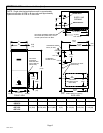
Interior Make−Up Box Installation
Figure 9
LEFT SIDE
RIGHT SIDE
MAKE−UP
BOX
MAKE−UP
BOX