


Page 6
505047 09/06
Return Air Opening Guidelines
NOTE − Do not bring in air from the back of the unit. Return
air can be brought in from the sides or bottom only.
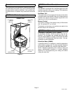
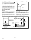
Bottom Return
If the air handler is installed on a platform with bottom re-
turn, make an airtight seal between the bottom of the air
handler and the platform to ensure that the air handler op-
erates properly and safely. Use aluminum tape or mastic
between the plenum and the air handler cabinet to ensure
a tight seal. The air handler is equipped with a removable
bottom panel to facilitate installation.
Side Return
For side return air applications, cut the air handler cabinet
at the maximum return air dimensions shown on page 2.
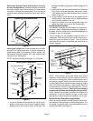
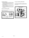
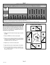
See figure 3 for a typical side inlet arrangement with a tran-
sition and filter.
NOTE − Single side inlet applications result in approxi-
mately a 4 percent reduction of CFM on B−size units and
approximately a 5 percent reduction of CFM on C−size
units:
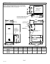
Figure 3
Side Return Air With Transition And Filter
RETURN AIR
PLENUM
TRANSITION
20" X 25" X 1"
(508MM X 635MM X 25MM)
CLEANABLE FILTER
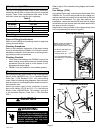
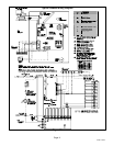
Return Air Base
For return air with the optional return air base (RAB), see
figure 4 (and refer to installation instructions provided with
Return Air Base kit).
*NOTE − Both unit and return air base openings must be
connected to and entirely covered by a single plenum or
IAQ accessory opening. Optional side return air filter kits
cannot be used with RAB Return Air Base.
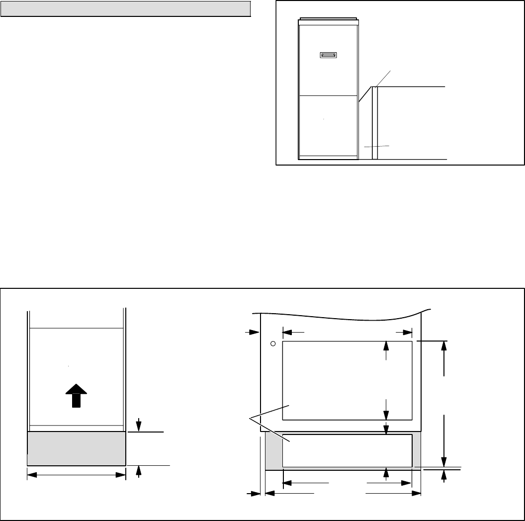
Optional Return Air Base and Unit Dimensions − Inches (mm)
Figure 4
*Unit
Opening
AIR FLOW
FRONT VIEW
27−5/8 (702)
4
(102)
*23 (584) Overall (Max.)
*Minimum
11 (279)
*Maximum
14 (356)
RETURN
AIR BASE
23 (584)
7−1/4
(184)
7/8 (22)
3/4
(19)
*Height varies
with plenum or
IAQ accessory
height.
Side Return
Air Openings
(Either Side)
17 (432) RAB−B (98M60)
21 (533) RAB−C (98M58)
SIDE VIEW
*Base
Opening
5−5/8
(143)
NOTE − IN SIDE RETURN
APPLICATIONS, THE RAB
IS REQUIRED FOR 100%
CFM CAPACITY.