


NOTE: DIAGRAMS & ILLUSTRATIONS ARE NOT TO SCALE.
8
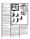
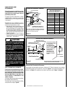
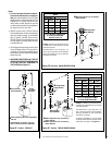
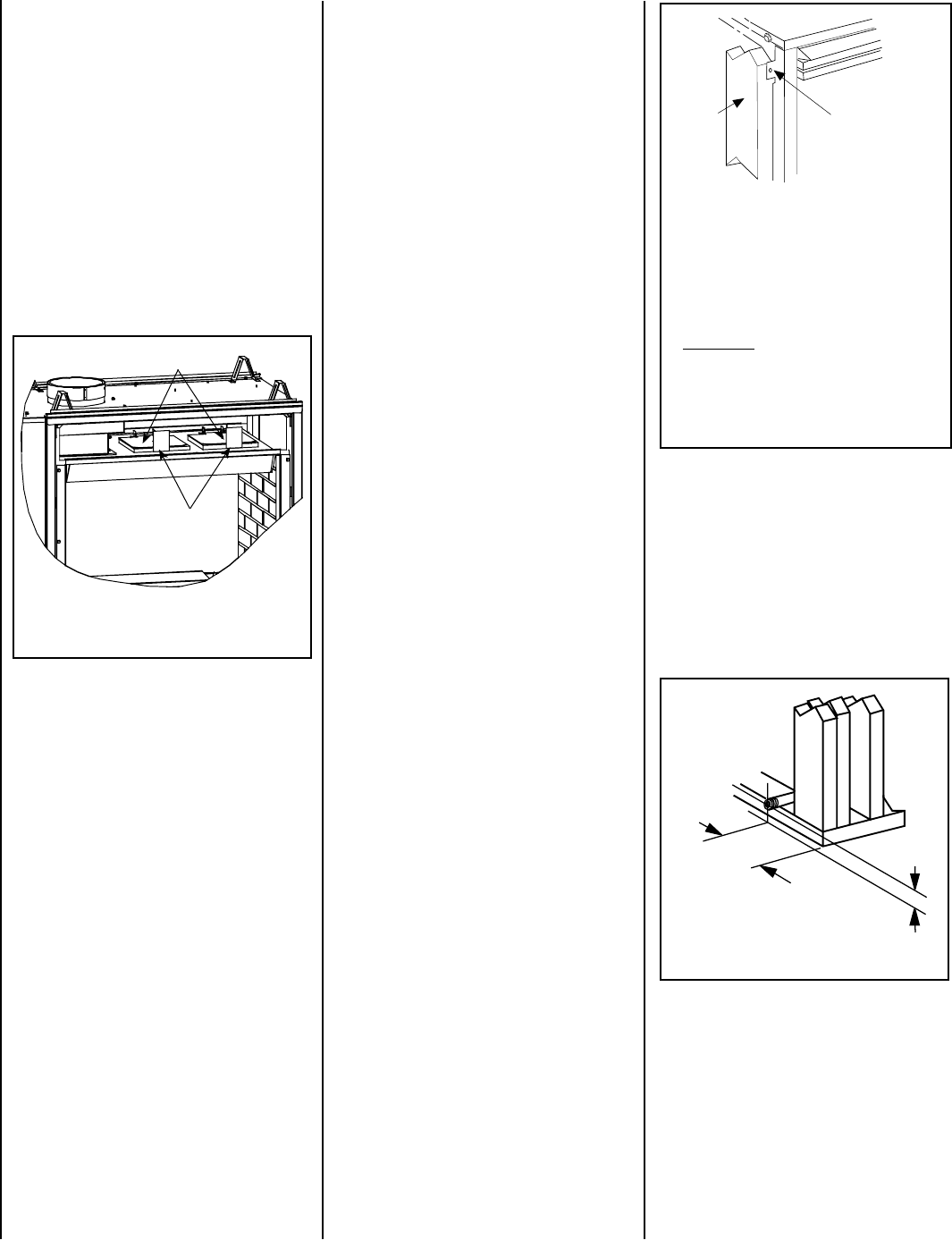
Also see Figure 14.
6 1/2"
(152 mm)
3"
(76 mm)
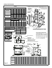
Figure 13 - ROUTE GAS LINE
Right Side Front
Corner of Fire-
place Framing
Continued on
Page 10.
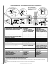
REMOVE
CARDBOARD
BEFORE USING
REMOVE
CARDBOARD
BEFORE USING
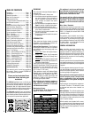
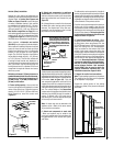
Pressure Relief Plates
Remove Cardboard Before
Using Appliance
Figure 11
Note: See-Through Model Shown
TYPICAL INSTALLATION SEQUENCE
The typical sequence of installation follows,
however, each installation is unique resulting
in variations to those described.
See the Page numbers references in the follow
-
ing steps for detailed procedures.
Step 1. (Page 8) Construct the appliance fram-
ing. Position the appliance within the framing
and secure with nailing brackets.
Step 2. (Page 8) Route gas supply line to ap-
pliance location.
Step 2. ROUTING GAS LINE
Route a 1/2" (13 mm) gas line along the inside
of the right side framing as shown in Figure
13. Gas lines must be routed, constructed and
made of materials that are in strict accordance
with local codes and regulations. All appliances
are factory-equipped with a flexible gas line
connector and 1/2 inch shutoff valve. (See
Step 6 on Page 24 ).
Step 3. (Page 11) Install the vent system and
exterior termination.
Step 4. (Page 23) Field Wiring
a. Millivolt Appliances – Install the operating
control switch (not factory provided) and
bring in electrical service line for forced air
circulating blower (optional equipment).
b. Electronic Appliances – Field wire and
install operating control switch.
Step 5. (Page 23) Install blower kit (optional
equipment).
Step 6. (Page 24) Make connection to gas
supply.
Step 7. (Page 25) Install the logs, decorative
volcanic stone and glowing embers.
Step 8. (Page 26) Checkout appliance opera-
tion.
Step 9. (Page 29) Install glass door frame
assembly.
Step 10. (Page 29) Adjust burner to ensure
proper flame appearance.
Step 11. (Page 30) Install the hoods.
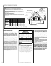
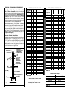
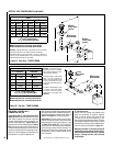
Step 1. FRAMING
Frame these appliances as illustrated in Figures
14 & 15 on Pages 9 & 10 (Figure 15 applies to
corner framing installations only). All framing
details must allow for a minimum clearance
to combustible framing members as shown in
Table 8 on Page 7.
If the appliance is to be elevated above floor
level, a solid continuous platform must be
constructed.
Headers may be in direct contact with the
appliance top spacers but must not be sup
-
ported by them or notched to fit around them.
All construction above the appliance must be
self supporting.
DO NOT use the appliance for
structural support.
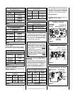
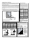
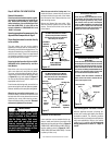
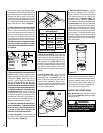
The fireplace should be secured to the side
framing members using the unit's nailing
flanges - one top and bottom on each side of
the fireplace front. See
Figure 12. Use 8d nails
or their equivalent.
Figure 12
Note: The nailing flanges, combustible members
and screw heads located in areas directly adjacent
to the nailing flanges, are EXEMPT from the 1/2”
clearance to combustible requirements for the
firebox outer wrapper
. Combustible framing may be
in
direct contact with the nailing flanges and may
be located closer than 1/2” from screw heads and
the firebox wrapper in areas adjacent to the nailing
flanges. Frame the opening to the exact dimensions
specified in the framing details of this manual.
Side
Framing
Unit Nailing Flange
(No clearance to
combustible
framing is required)
Left Side Front Corner of Fireplace Shown
(Right Side Requirements the Same)
Unit Being Secured By Its Nailing Flanges
To The Framing
DETAILED INSTALLATION STEPS
The appliance is shipped with all gas controls and
components installed and pre-wired. Remove
the shipping carton, exposing the front glass
door. Remove the top and bottom louvered
control panel per instructions on
Page 25 (see
Control Compartment Access / Louver Panel
Instructions). Remove the cardboard from
underneath the pressure relief plates (in area
behind top louver panel, See Figure 11). Open
the two latches (located under the firebox floor)
securing the glass door. Remove the door by
tilting it outward at the bottom and lifting it up.
Set the door aside protecting it from inadvertent
damage.
See Figure 57 on Page 29.