


3
NOTE: DIAGRAMS & ILLUSTRATIONS ARE NOT TO SCALE.
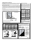
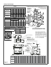
Electronic Models -
Electronic models have a fixed rate gas valve.
Input of electronic models is shown in Table 3.
Electronic Models with Fixed Rate Gas Valve
Natural and Propane Gas
Model Series Input Rate
(BTU / HR)
LMDVT-3328
LMDVR-3328
17,500
LMDV-3530 20,000
LMDV-4035 27,000
Table 3
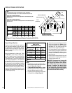
Burner Orifice Sizes
Elevation 0-4500 feet ( 0-1372 meters)
Model
Series
Nat.Gas
drill size (inches)
Propane
drill size (inches)
LMDVT-3328
LMDVR-3328
#45 (.082")
*
39L66 •
(.048")
*
99K780 •
LMDV-3530
#44 (.086")
*
60J8001 •
#55 (.052")
*
19L5201 •
LMDV-4035
#37 (.104")
*
24M1001 •
1/16"
(.062")
*
21L0101 •
Table 7
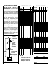
Inlet Gas Supply Pressure
(all models)
Fuel # Minimum Maximum
Natural Gas
5.0" WC
(1.24 kPa)
10.5" WC
(2.61 kPa)
Propane
11.0" WC
(2.74 kPa)
13.0" WC
(3.23 kPa)
Table 4
Gas Pressure - All Models
Tables 4, 5 and 6 show the appliances' gas
pressure requirements:
Manifold Gas Supply Pressure
(millivolt models)
Fuel # Low High
Natural
Gas
(Lo) 2.2" WC
(.55 kPa)
(Hi) 3.5" WC
(.87 kPa)
Propane
(Lo) 6.3" WC
(1.57 kPa)
(Hi) 10.0" WC
(2.49 kPa)
Table 5
Manifold Gas Supply Pressure
(electronic models)
Fuel # Maximum Manifold Pressure
Natural Gas (Hi) 3.5" WC (.87 kPa)
Propane (Hi) 10.0" WC (2.49 kPa)
Table 6
Test gauge connections are provided on the
front of the millivolt gas control valve, identi
-
fied IN for the inlet and OUT for the manifold
side. A 1/8" NPT Test gauge connection
is provided at the inlet and outlet side of
the electronic gas control valve.
Orifice Sizes - Sea Level to High Altitude
(All Models)
These appliances are tested and approved for
installation at elevations of 0-4500 feet (0-1372
meters) above sea level using the standard burner
orifice sizes (marked with an "*" in
Table 7). For
elevations above 4500 feet, contact your gas
supplier or qualified service technician .
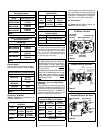
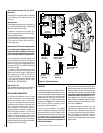
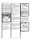
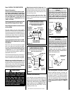
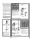
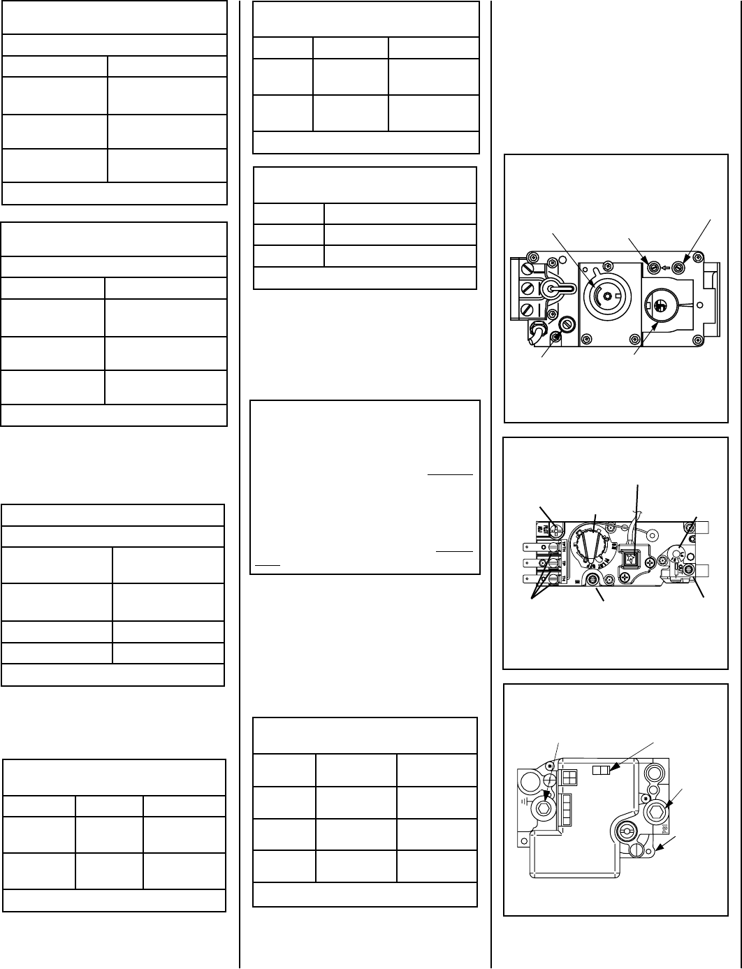
Gas Valve Diagrams
See
Figures 1 & 2 for Millivolt models and
Figure 3 For Electronic Models.
Figure 3
Honeywell Electronic Gas Valve
F
F
O
N
I
P
S
I
NO
L
O
R
T
N
O
C
G
I
N
T
I
ER
Manifold Pressure
Port
ON / OFF Switch
Inlet
Pressure
Port
Electronic
Gas
Control
Valve
O
N
O
F
F
P
I
L
O
T
L
O
H
I
Figure 2
GAS CONTROL
KNOB
CONVERTIBLE
HI/LO REGULATOR
(adjusts flame height
and heat output)
INLET
PRESSURE
TAP
PILOT
ADJUSTMENT
SCREW
WIRING
TERM-
INALS
OUTLET
PRESSURE
TAP
TP/TH
PIEZO
IGNITER
TH
TP
Honeywell Millivolt Gas Valve
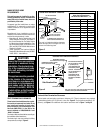
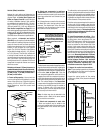
These appliances must be isolated from the
gas supply piping system (
by closing their
individual manual shut-off valve) during any
pressure testing of the gas supply piping
system at test pressures equal to or
less than
1/2 psig (3.5 kPa).
These appliances and their individual shut-off
valves
must be disconnected from the gas
supply piping system during any pressure
testing of that system at pressures
greater
than 1/2 psig (3.5 kPa).
Install the appliance according to the regulations
of the local authorities having jurisdiction and,
in the USA, the National Fuel Gas Code NFPA 54
/ ANSI Z223.1 - latest edition or, in Canada, the
CAN1-B149.1 and .2 codes - latest edition.
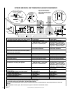
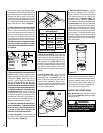
Input (BTU) Manually-Modulated Gas
Valves (millivolt models)
NATURAL GAS
Models Input Rate (BTU / HR)
LMDVT-3328CNM
LMDVR-3328CNM
17,500 high
11,700 low
LMDV-3530CNM
20,000 high
12,800 low
LMDV-4035CNM
27,000 high
18,500 low
Table 1
Input (BTU) Manually-Modulated Gas
Valves (millivolt models)
PROPANE GAS
Models Input Rate (BTU / HR)
LMDVT-3328CPM
LMDVR-3328CPM
17,500 high
14,000 low
LMDV-3530CPM
20,000 high
15,200 low
LMDV-4035CPM
27,000 high
21,500 low
Table 2
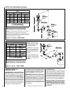
H
I
L
O
W
H
TPT
HT
P
T
P
I
L
O
T
P
I
L
O
T
O
N
it
O
F
F
IN
OUT
Manifold Pressure Tap
Inlet Pressure Tap
SIT Millivolt Gas Valve
Pilot Adjustment
Screw
HI/LO Variable
Flame Height
Adjustment
Main Gas
Control Knob
OFF/PILOT/ON
Figure 1
* Standard size installed at factory
• Part /Cat. Number