


36
NOTE: DIAGRAMS & ILLUSTRATIONS ARE NOT TO SCALE.
NOTE: DIAGRAMS & ILLUSTRATIONS ARE NOT TO SCALE.
Printed in U.S.A. © 2005 by LENNOX HEARTH PRODUCTS
P/N 850,029M REV. G 05/2008
Lennox reserves the right to make changes at any time, without notice, in design,
materials, specifications, prices and also to discontinue colors, styles and products.
Consult your local distributor for fireplace code information.
1110 West Taft Avenue • Orange, CA 92865
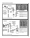
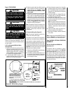
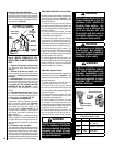
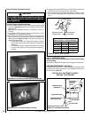
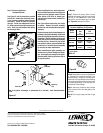
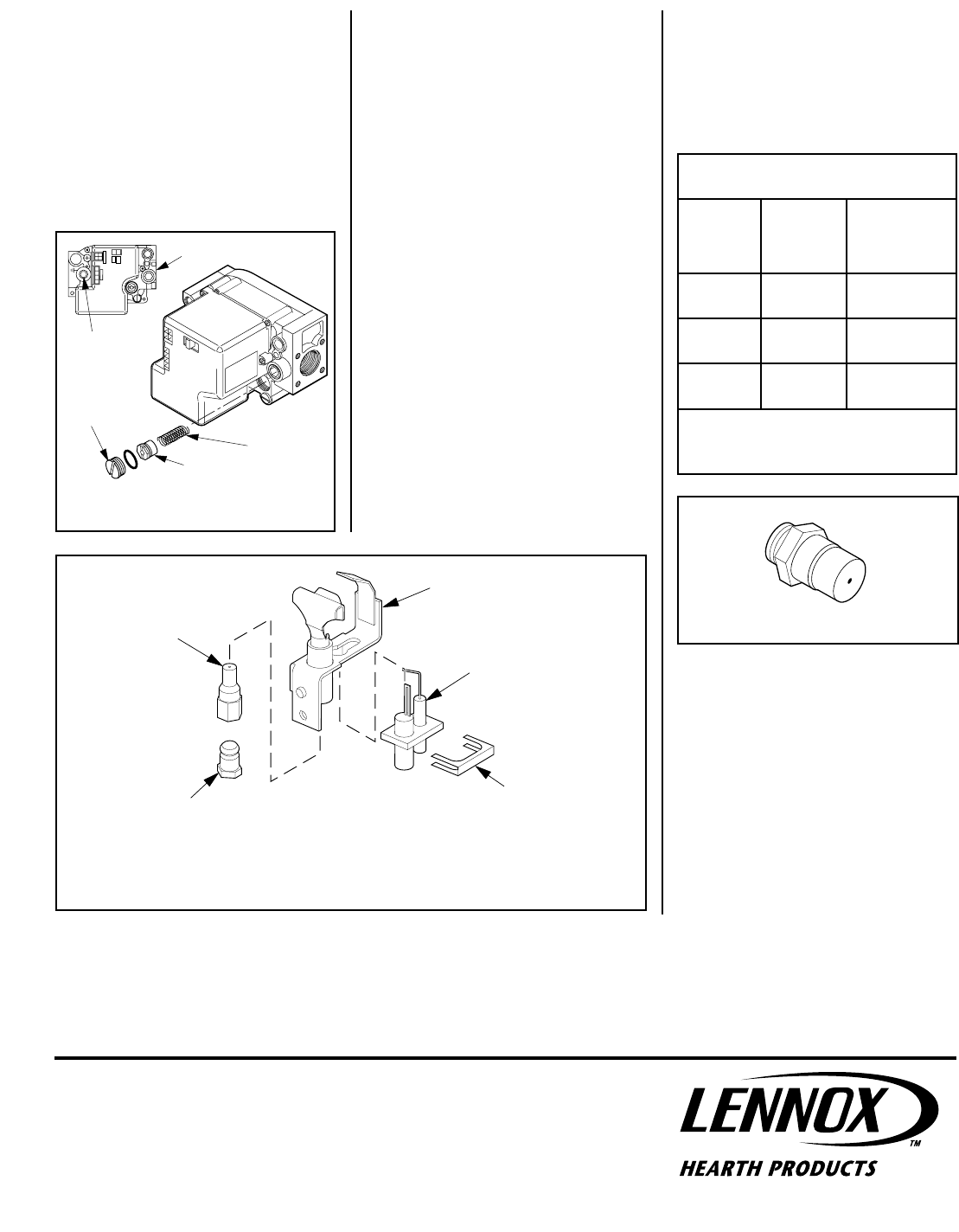
Figure 68
Retaining
Clip
Ignitor
Assembly
Pilot
Assembly
Pilot
Orifice
Flare Nut
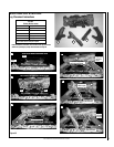
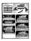
Figure 69
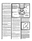
Step 8. Reassemble all removed components
by reversing the procedures outlined in the
preceding steps. Use pipe joint compound or
Teflon tape on all pipe fittings before installing
(ensure propane resistant compounds are used
in propane applications, do not use pipe joint
compounds on flare fittings).
Step 9. Attach the conversion label provided
in the conversion kit to the rating plate on the
appliance.
Step 10. Turn on gas supply and test for gas
leaks.
All Models
Step 7. Remove the burner orifice from the
manifold and replace it with the one provided
with the kit. See
Table 14 for orifice sizes
required for use with natural gas or propane
gas. Figure 69 illustrates the orifice.
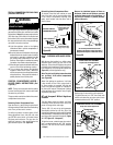
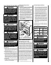
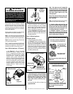
Step 6. Electronic Appliances -
Honeywell Systems
See Figure 67 and the instructions provided
with the kit. Remove the slotted cap screw,
o-ring, pressure-regulating adjusting screw
and spring. Retain all parts for possible
later use. Install new components from the
kit. Black cap and red spring for propane gas
units. Silver cap and stainless steel spring
for natural gas units.
Before installing the cap, attach manometer
to the manifold side pressure test fitting and
adjust screw until pressure reads 3.5 inches
water column (0.87 kPa) for natural gas,
and 10.0 inches water column (2.49 kPa) for
propane gas.
See Figure 68 and replace the pilot orifice
as follows: Remove the Igniter assembly
retainer clip, and carefully remove the Igniter
assembly.
Exercise extreme care to prevent damage to or
breakage of the Igniter assembly. Remove the
screw securing the pilot assembly to its mount-
ing bracket. Back off the flare nut at the end
of the pilot gas line to free the pilot assembly
from the gas line. Remove the pilot orifice
and replace it with the one provided with the
conversion kit. Reinstall the pilot assembly
by reversing the steps detailed here.
When reinstalling the Igniter assembly, use
extreme care to prevent damage and break-
age. Do not apply any leverage to the Igniter
assembly while restoring the retainer clip to
its original position.
Figure 67
Spring
Adjusting
Screw
Slotted
Cap
P
S
I
OFF
I
ON
CONTROL
I
G
N
I
T
E
Manifold
Pressure
Test Port
Inlet Pressure Test Port
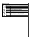
Burner Orifice Sizes
Elevation 0-4500 feet ( 0-1372 meters)
Model
Series
Natural
Gas
drill
sizez(inches)
Propane
Gas
drill size (inches)
LMDVT-3328
LMDVR-3328
#45 (.082")
*
39L66 •
1.2mm (.048")
*
99K78 •
LMDV-3530
#44 (.086")
*
60J8001 •
#55 (.052")
*
19L5201 •
LMDV-4035
#37 (.104")
*
24M1001 •
1/16"
(.062")
*
21L0101 •
* Standard size installed at factory
• Part /Cat. Number
Table 14
Note: If the Igniter is damaged, a replacement kit is available - order Catalog Number
87L54.