


NOTE: DIAGRAMS & ILLUSTRATIONS ARE NOT TO SCALE.
18
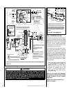
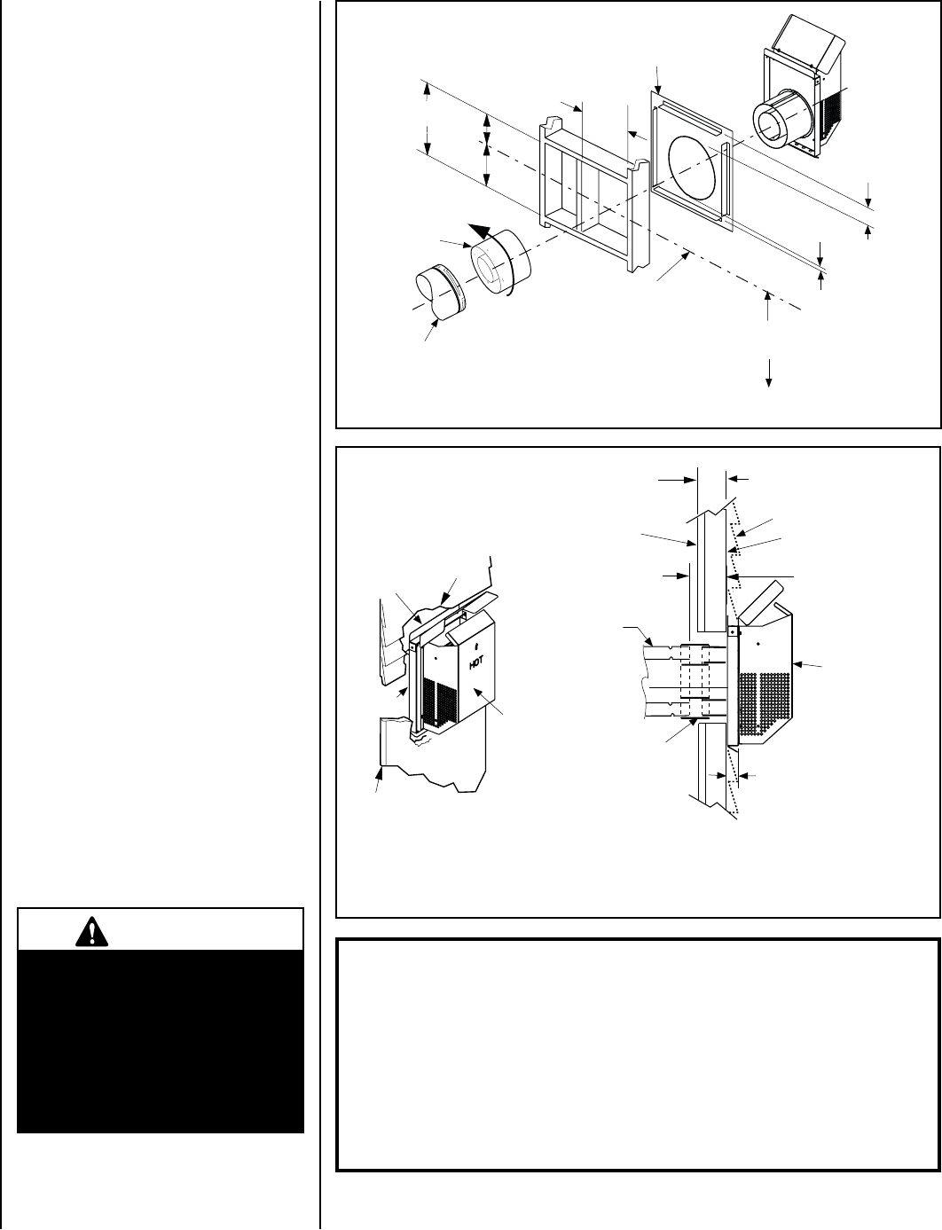
J. Assemble vent run to exterior wall - If not
previously measured, locate the center of the
vent at the exterior wall. Prepare an opening as
described in
Step B. Assemble the vent system
to point where the terminus of the last section is
located relative to the exterior surface to which
the termination is to be attached as shown in
Figure 35 and Table 12 on Pages 18 & 19.
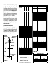
If the terminus of the last section is not within
this distance, use the
telescopic vent section
SV4.5LA, as the last vent section. For wall
thicknesses greater than that shown in
Figure
35, refer to Table 12 on Page 19. This Table
lists the additional venting components needed
(in addition to the termination and adapter) for
a particular range of wall thicknesses.
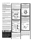
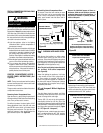
K. Attach termination adapter - Attach the
adapter (adapter - SV4.5RCH - provided with the
termination) to the vent section or telescoping
vent section), elbow or appliance collar as shown
in
Figure 34 in the same manner as any SV4.5
vent component (refer to
Step E).
L. Install Firestop/Spacer at exterior wall
- When using the square termination, install
SV4.5HF (Secure Vent), SF4.5HF (Secure Flex)
Firestop/Spacer over the opening at the exterior
side of the framing, long side up, with the 3 inch
spacer clearance at the top as shown in
Figure
34, and nail into place.
(The Firestop/Spacer may also be installed over
the opening at the interior side of framing).
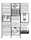
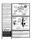
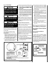
M. Install the Square Termination (SV4.5HT-2)
Install the square termination - For the last step
, from outside the exterior wall, slide the collars
of the termination onto the adapter (the outer
inside the outer and the inner outside the inner)
until the termination seats against the exterior
wall surface to which it will be attached. Orient
the housing of the termination with the arrow
pointed upwards. Secure the termination to
the exterior wall.
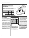
The horizontal termination
must not be recessed into the exterior wall
or siding by more than the 1-1/4" (32 mm) as
shown in
Figure 35.
SV4.5 HT-2
Termination
SV4.5 HT-2
Termination
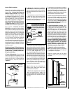
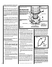
Horizontal terminations have been designed to perform in a wide range of weather condi-
tions. Our terminations meet or exceed industry standards.
When selecting the locations of your horizontal terminations, do not place the termina-
tion where water from eaves and adjoining rooflines may create a heavy flow of cascad-
ing water onto the termination cap. If the cap must be placed where the possibility of
cascading water exists, it is the responsibility of the builder to direct the water away
from the termination cap by using gutters or other means.
Take care to carefully follow the installation instructions for the termination, including
the use of silicone caulking where required.
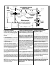
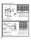
Figure 35
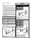
Figure 34 - INSTALLING SQUARE HORIZONTAL TERMINATION (SV4.5HT-2)
Siding
Stucco
1-1/4” Maximum Recess of
Square Termination
into Exterior Finishing Material
Exterior Surface of
Framing
Exterior Surface of Siding
Maximum Extent of
Vent Run Sections
Relative to Exterior
Surface of Framing
Interior Surface of
Finished Wall
Last Vent Section.
Use Telescopic Vent
Section (SV4.5LA), If
Necessary
Adapter
SV4.5RCH
Use silicone caulking to seal
the top and sides of the
termination, up to the
underlayment, stucco, or
masonry wall surface.
Caulk
Caulk
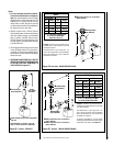
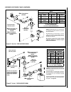
Maximum Wall Thickness
10 in. (254 mm)
6 in. to 9-1/4 in.
(152 to 235 mm)
10-1/2"
(267mm)
7"
(178)
5-1/8"
(130 mm)
12-1/8"
(308 mm)
Note: Centerline of Vent Piping is
NOT the Same as the Centerline of
the Framed Opening.
6 to 48 inch Vent Section,
Telescopic vent section,
Elbow or Appliance Collar
Base of Appliance
3"
(76 mm)
1"
(25.4 mm)
Adapter
SV4.5RCH
To help minimize water infiltration it is
recommended that the Firestop/Spacer
(SV4.5HF) be installed on the exterior
side of the wall.
Venting Connection and Exterior Wall Recessing of the Horizontal Square
Termination (SV4.5HT-2).
See Figure 14 on Page 9 for Min.
Distance to Base of Appliance.
SV4.5 HT-2
Termination
v
For thicknesses greater
than 10", see Table 12
IMPORTANT
The vent termination is hot while
in operation and for a period of
time following the use of the fire-
place. To prevent contact with hot
surfaces, we recommend the use
of a Termination Guard. See Items
12 and 13 on Page 31. This can be
purchased at your local dealer.