


NOTE: DIAGRAMS & ILLUSTRATIONS ARE NOT TO SCALE.
26
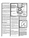
WARNING
The size and position of the log
set was engineered to give the
appliance a safe, reliable and
attractive flame pattern. Any
attempt to use a different log
set in the fireplace will void
the warranty and will result in
incomplete combustion, soot-
ing, and poor flame quality.
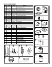
REFERENCE
Firebox Accessories / Parts
Cat. No. Model No. Description
88L53 FGE Bag of Glowing Embers
(1 oz. rockwool)
H3696
Vermiculite, Bag (2 liters)
80L42 FDVS
Bag of Decorative
Volcanic Stone
Table 13
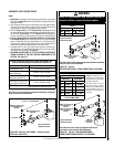
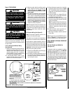
Glowing Embers
Bag of Glowing
Embers (rockwool)
Separate into Quarter
Size (separate) Pieces
Step 8. INSTALL VERMICULITE, VOL-
CANIC STONE, GLOWING EMBERS AND
LOGS
1. Remove the front glass enclosure panel
(see
Removing Glass Enclosure Panels on
Page 31).
2. Remove log set box from firebox. Next,
remove embers and vermiculite from control
compartment.
Handle logs carefully to prevent
breakage.
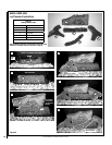
3. Install Vermiculite - Place some vermiculite
on the firebox floor around the burner (the
entire bag of vermiculite will NOT be used).
See
Figures 55 & 56. DO NOT PLACE ANY
VERMICULITE ON THE BURNER. Mound
up a portion of the vermiculite in front of the
burner.
4. Install decorative volcanic stone - Sprinkle
the decorative volcanic stone (dark colored)
on top of the vermiculite (light colored) in a
pleasing pattern (see
Figures 55 & 56).
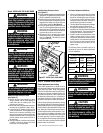
5. Placement of Glowing Embers -
Separate the Embers (rockwool) into pieces
about the size of a quarter (see
Figure 54).
Keep the pieces fluffed up, not matted. Dis
-
tribute these pieces over the surface of the
burner, as shown in
Figures 55 & 56. Do not
use more than is necessary. Ensure that the
main burner slots remain uncovered by the
ember material.
Note: This appliance is provided with enough
Glowing Embers for several applications, do
not use all that is in a new bag at one time. For
best glowing effect, replace the ember material
annually.
6. Placement of Logs and Twigs -
All logs that have locating notches or slots to help
ensure that they are properly positioned. All top
logs that rest on lower logs, do so over notches,
indents or pins. Proper twig placement is critical
to prevent sooting. Twigs should be placed in
the gaps between the flame peaks and should be
positioned so they do not impinge the flames.
Figure 54
WARNING
This appliance is not designed
to burn wood. Any attempt to
do so could cause irreparable
damage to appliance and prove
hazardous to your safety.
WARNING
If logs are not installed according
to the log installation instruc-
tions, flame impingement and
improper combustion could
occur and result in soot and/or
excessive production of carbon
monoxide (CO), a colorless,
odorless, toxic gas.
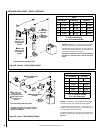
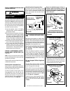
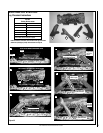
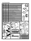
LMDV-3328 & LMDV-3530 - Install as Follows
Carefully position the ceramic fiber logs and twigs
over the burner as shown in
Figure 55. Logs
should be placed in the order shown and per the
following instructions.
1. Place the rear log (A) as shown. Position
the 2 notches on the bottom of the log over the
2 corresponding locating brackets against the
back wall of firebox.
2. Place the left log (B) as shown. The notch
on the bottom of the log should fit over the
corresponding locating bracket.
3. Place the right log (E) as shown. The hole
on the back of the log should fit over the cor
-
responding pin on the rear log (A). Make sure
that the log is positioned so it aligns to the sides
of the gas ports on the corner of the burner.
4. Place the left center log (C) as shown. The
forked end of the log fits into the corresponding
notch on rear log (A). The slot on the other
end (bottom) of log fits over the corresponding
locating bracket on the sub-floor.
5. Place the right center log (D) as shown. One
end of the log fits into the corresponding indent
on the right log (E). The slot on the other end
(bottom) of log fits over the corresponding
locating bracket on the sub-floor.
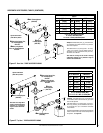
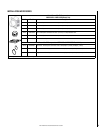
LMDV-4035 - Install as Follows
Carefully position the ceramic fiber logs and twigs
over the burner as shown in Figure 56. Logs
should be placed in the order shown and per the
following instructions.
1. Position the center log (C) onto the 2 cor-
responding location pins on the burner.
2. Place the rear log (A) as shown. Position
the 2 notches on the bottom of the log over the
2 corresponding locating brackets against the
back wall of firebox.
3. Place the left log (B) as shown. The notch
on the bottom of the log should fit over the
corresponding locating bracket.
4. Place the right log (E) as shown. The notch
on the bottom of the log should fit over the
corresponding locating bracket. Make sure that
the log is positioned so it aligns to the sides of
the gas ports on the corner of the burner.
5. Place the center front log (D) as shown. The
slot in the bottom of the log fits over the cor-
responding location bracket on the sub-floor.
WARNING
DO NOT attempt to install the logs
until the appliance installation
has been completed, the gas line
connected and tested for leaks
and the initial burner operation
has been checked out.
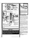
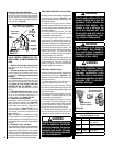
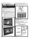
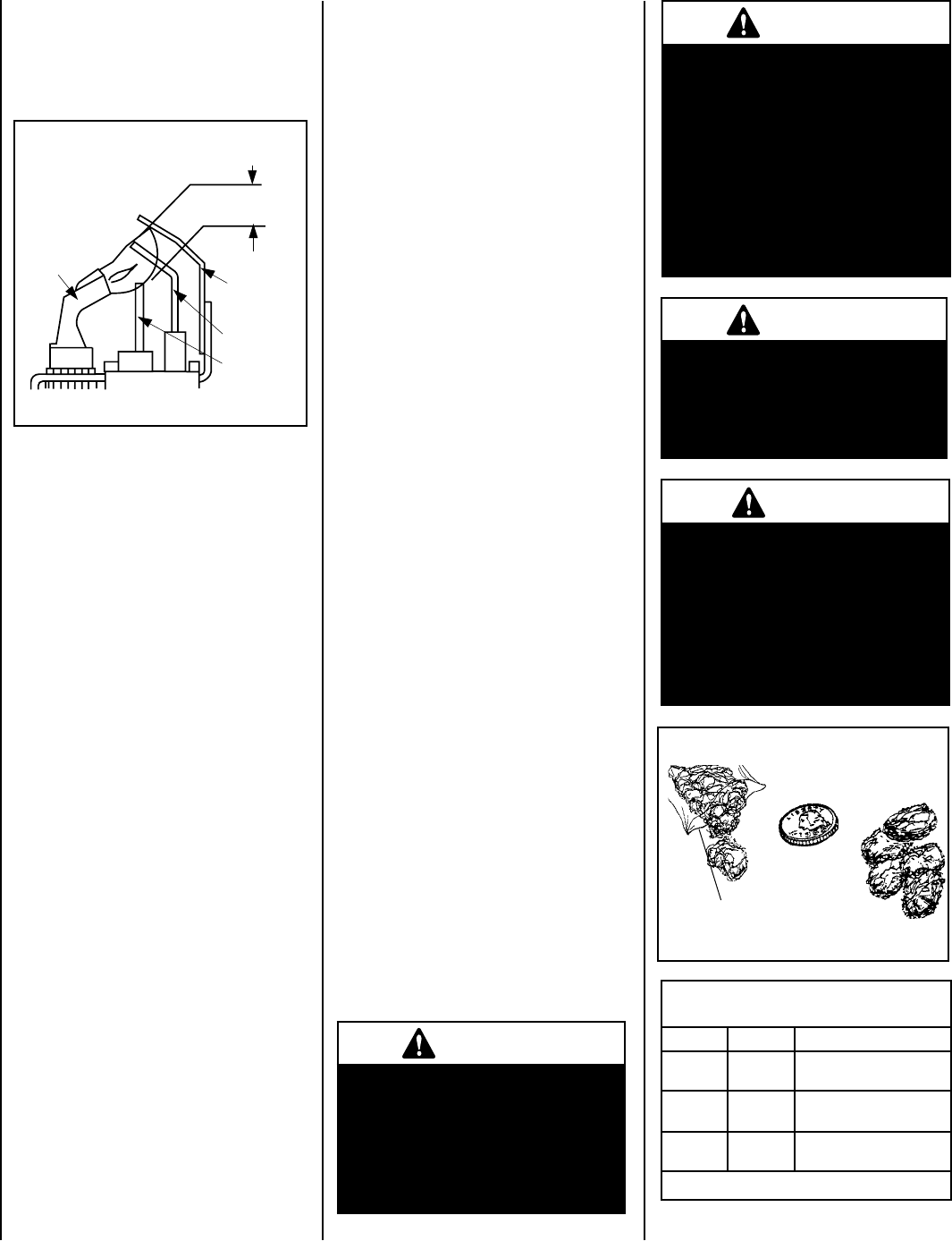
Figure 53
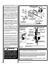
3/8" to 1/2"
(9 -13 mm)
Ground
Electrode
Flame Rod
Hot Surface
Igniter
Proper Flame
Adjustment
Pilot
Nozzels
ELECTRONIC PILOT ASSEMBLY
Proper Pilot Flame Appearance
Electronic Appliance Checkout
To light the burner, turn ‘ON’ the optional remote
wall switch and turn the gas control switch to
the “ON” position. Ensure the Igniter lights the
pilot. The pilot flame should engulf the flame
rod as shown in
Figure 53.