


NOTE: DIAGRAMS & ILLUSTRATIONS ARE NOT TO SCALE.
16
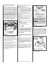
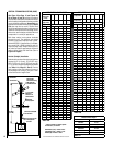
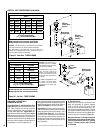
A. Plan the vent run -
Analyze the vent routing and determine the
types and quantities of sections required
4-1/2" (114 mm), 10-1/2" (267 mm), 22-1/2"
(572 mm), 34-1/2" (876 mm) and 46-1/2" (1181
mm) net section lengths are available. Plan the
vent lengths so that a joint does not occur at the
intersection of ceiling or roof joists. Make allow
-
ances for elbows as indicated in
Figure 24.
Maintain a minimum 1" (25 mm) clearance to
combustibles on the vertical sections. Clear-
ances for the horizontal runs are; 3" (76 mm)
on top, 1" (25 mm) on sides, and 1" (25 mm)
at the bottom.
H1
V
V1
H
u
Ceiling
Firestop / Spacer
(SV4.5VF)
v
Wall Firestop/
Spacer (SV4.5HF)
u
Ceiling
Firestop / Spacer
(SV4.5VF)
V
H
1
H
V
1
u
Ceiling
Firestop / Spacer
(SV4.5VF)
v
Wall Firestop/
Spacer (SV4.5HF)
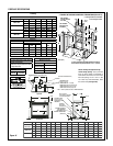
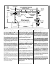
Example: If 20 feet total (H+H
1
)
horizontal vent run is needed,
then 4 feet minimum of (V) verti-
cal vent will be required.
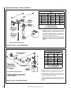
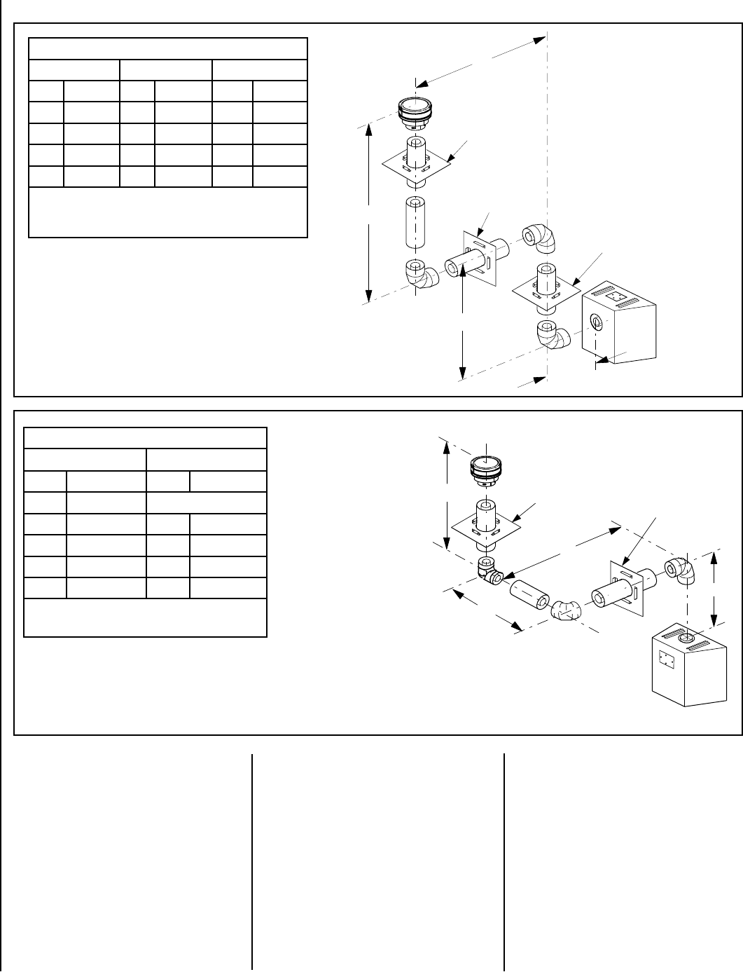
This table shows a 1(V) to 5(H)
ratio. For every 1 foot of (V)
vertical, you are allowed 5 feet
of (H+H
1
) horizontal run up to
a maximum total horizontal run
of 20 feet.
An elbow is acceptable as 1 foot
of vertical rise except where
an elbow is the only vertical
component in the system. See
Figure 37.
Table D
H + H
1
Maximum
V Minimum
feet (meter) feet (meter)
5 (1.524) Elbow Only
5 (1.524) 1 (0.305)
10 (3.048) 2 (0.610)
15 (4.572) 3 (0.914)
20 (6.096) 4 (1.219)
H + H
1
= 20 feet (6.096 m) Max.
V + V
1
+ H + H
1
= 40 ft. (12.192 m) Max.
u When using Secure Flex, use Firestop / Spacer SF4.5VF
v When using Secure Flex, use Firestop / Spacer SF4.5HF
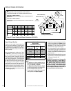
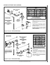
Table C
H+H
1
Maximum H
Maximum V Minimum
feet (meter) feet (meter) feet (meter)
5 (1.524) 2 (0.610) 1 (0.305)
10 (3.048) 4 (1.219) 2 (0.610)
15 (4.572) 6 (1.829) 3 (0.914)
20 (6.096) 8 (2.438) 4 (1.219)
V + V
1
+ H + H
1
= 40 feet (12.2 m) Max
H = 8 feet (2.438 meters) Max.
H + H
1
= 20 feet (6.096 meters) Max.
Example: If 20 feet total (H+H
1
) horizontal vent run is needed,
then 4 feet minimum of (V) vertical vent will be required.
This table shows a 1(V) to 5(H) ratio. For every 1 foot of (V)
vertical, you are allowed 5 feet of (H+H
1
) horizontal run up to a
maximum total horizontal run of 20 feet.
u When using Secure Flex, use Firestop / Spacer SF4.5VF
v When using Secure Flex, use Firestop / Spacer SF4.5HF
Figure 32 - Top Vent - THREE ELBOWS
Figure 31 - Rear Vent - THREE ELBOWS
VERTICAL VENT FIGURES/TABLES (CONTINUED)
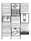
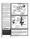
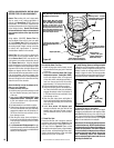
HORIZONTAL (OUTSIDE WALL)
TERMINATION SYSTEM
Figure 33 on Page 17, and Figures 34 to 42 on
Pages 18 to 21 and their associated Horizontal
Vent Table illustrate the various horizontal
venting configurations that are possible for
use with these appliances.
Secure Vent pipe
applications are shown in these Figures;
Secure
Flex pipe may also be used. A Horizontal Vent
Table summarizes each system’s minimum and
maximum vertical and horizontal length values
that can be used to design and install the vent
components in a variety of applications.
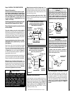
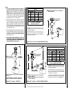
Both of these horizontal vent systems terminate
through an outside wall. Building Codes limit or
prohibit terminating in specific areas. Refer to
Figure 7 on Page 6 for location guidelines.
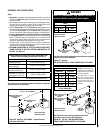
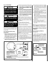
Secure Vent SV4.5 direct vent system compo-
nents are unitized concentric pipe components
featuring positive twist lock connection, (
refer
to Figure 22 on Page 13). All of the appli-
ances covered in this document are fitted with
collars having locking inclined channels. The
dimpled end of the vent components fit over
the appliance collar to create the positive twist
lock connection.