


9
NOTE: DIAGRAMS & ILLUSTRATIONS NOT TO SCALE.
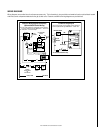
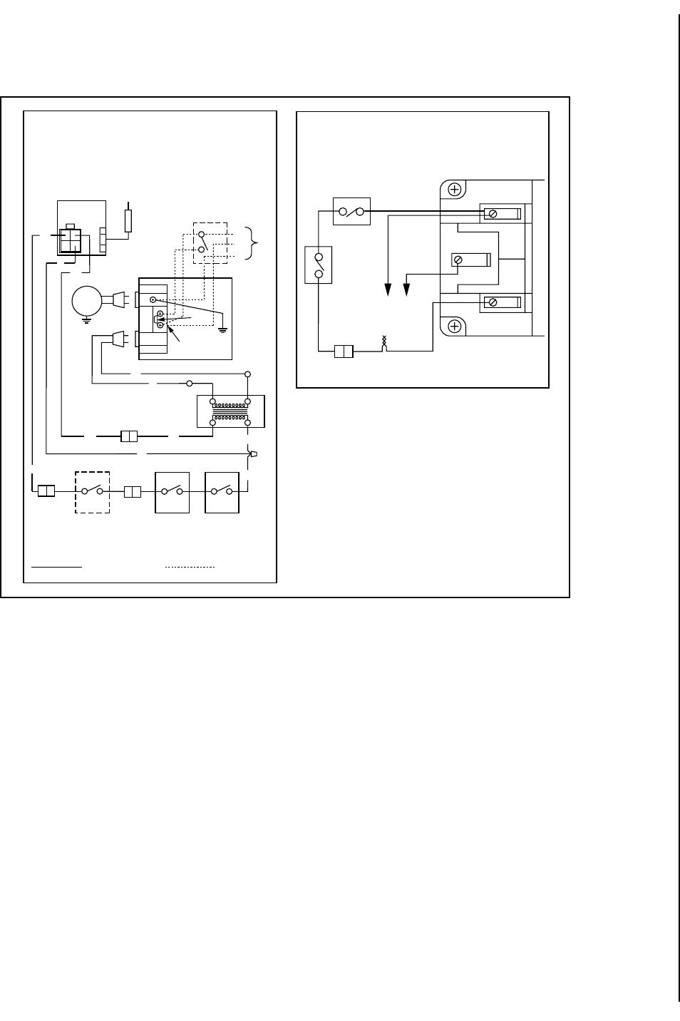
WIRING DIAGRAMS
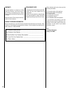
Wiring diagrams are provided here for reference purposes only. This information is also provided on schematics found on pullout labels located
within the control compartment attached to the gas control valve. Electronic and Millivolt wiring diagrams are provided here.
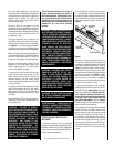
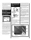
SIT Millivolt Wiring Diagram
* For Wall Switch Attachment Only.
If any of the original wire as supplied must be replaced, it
must be replaced with Type AWM 200°C – 18 GA. wire.
Thermopile
TH
TP
TH
TP
Limit
Switch
Damper Switch
BK
BK
BK
BK
WHT
*
1. If any of the original wire as supplied must be replaced,
1. it must be replaced with Type AWM 200°C – 18 GA. wire.
2. 120V, 60Hz – Less than 3 amps.
BK
Junction Box
Transf.
120 V.
24 V
Factory Wired
Field Wired
BL
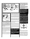
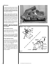
Electronic Wiring Diagram (Honeywell)
(Optional ON/OFF Switch Wiring)
R
BK
BL
To Opposite Side
OPT
FAN
G
W
OPT. ACCESSORY
SWITCH
120
VAC.
BK
LIMIT
SWITCH
W
Gas Valve
B
BL
OPTIONAL
ON/OFF SWITCH
OR
WALL SWITCH
R
R
IGNITER
CONTROL
PILOT
ASSEMBLY
Break
Off Tab
DAMPER
SWITCH
BK
BK
WHT
BK
BK