


3
NOTE: DIAGRAMS & ILLUSTRATIONS NOT TO SCALE.
Carbon Monoxide Poisoning: Early signs of
carbon monoxide poisoning are similar to
the flu with headaches, dizziness and/or nau-
sea. If you have these signs, obtain fresh air
immediately. Turn off the gas supply to the
appliance and have it serviced by a qualified
professional, as it may not be operating
correctly.
OPERATION AND CARE OF YOUR
APPLIANCE
1. Appliance operation may be controlled
through a remotely located optional wall switch.
Separate switches may provide independent
control for the remote controlled fireplace op-
eration (optional equipment).
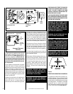
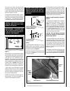
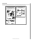
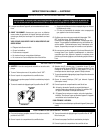
Figure 1
Operation of millivolt and electronic gas con-
trol systems are different. Before lighting and
operating your appliance determine if you have
a millivolt or electronic appliance.
Refer to
Figure 1
to access the gas control compart-
ment below the lower refractory panel. Milli-
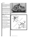
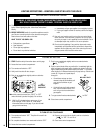
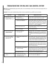
volt appliances will be fitted with one of the two
gas control valves shown in
Figure 2.
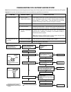
Appli-
ances with electronic systems will be fitted
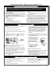
with the electronic valve shown in
Figure 3.
Familiarize yourself with the differing controls
for the valve your appliance uses.
To light millivolt appliances refer to the de-
tailed lighting instructions found in both En-
glish and French on
pages 10 and 11
of these
instructions respectively. Millivolt and elec-
tronic appliance lighting instructions may
also be found on the pull out labels attached
to the gas control valve located within the
gas control compartment. Refer to
Figure 2
to locate the appropriate location for the spark
ignitor used with your appliance.
If your appliance is equipped with an optional
remote wall switch or remote control kit the
appliance main burner may be turned on and
off with the wall switch or remote control. If
the appliance is not equipped with a wall or
remote control, the main burner must be turned
off and on with the gas control knob. Turn the
knob counter-clockwise from the PILOT posi-
tion to ON to light the main burner, and clock-
wise from ON to PILOT to turn off the main
burner.
WARNING: FAILURE TO COMPLY
WITH THE INSTALLATION AND OPER-
ATING INSTRUCTIONS PROVIDED IN
THIS DOCUMENT WILL RESULT IN AN
IMPROPERLY INSTALLED AND OP-
ERATING APPLIANCE, VOIDING ITS
WARRANTY. ANY CHANGE TO THIS
APPLIANCE AND/OR ITS OPERATING
CONTROLS IS DANGEROUS. IM-
PROPER INSTALLATION OR USE OF
THIS APPLIANCE CAN CAUSE SERI-
OUS INJURY OR DEATH FORM FIRE,
BURNS, EXPLOSION OR CARBON
MONOXIDE POISONING.
WARNING: B-VENT APPLIANCES ARE
NOT DESIGNED TO OPERATE IN NEGA-
TIVELY PRESSURED ENVIRONMENTS
(PRESSURE WITHIN THE HOME IS LESS
THAN PRESSURES OUTSIDE). SIGNIFI-
CANT NEGATIVELY PRESSURED ENVI-
RONMENTS CAUSED BY WEATHER,
HOME DESIGN, OR OTHER DEVICES
MAY IMPACT THE OPERATION OF THESE
APPLIANCES. NEGATIVE PRESSURES
MAY RESULT IN POOR FLAME APPEAR-
ANCE, SOOTING, DAMAGE TO PROP-
ERTY AND/OR SEVERE PERSONAL IN-
JURY. DO NOT OPERATE THESE APPLI-
ANCES IN NEGATIVELY PRESSURED
ENVIRONMENTS.
WARNING: CHILDREN AND ADULTS
SHOULD BE ALERTED TO THE HAZ-
ARDS OF HIGH SURFACE TEMPERA-
TURES. USE CAUTION AROUND THE
APPLIANCE TO AVOID BURNS OR
CLOTHING IGNITION. YOUNG CHIL-
DREN SHOULD BE CAREFULLY SUPER-
VISED WHEN THEY ARE IN THE SAME
ROOM AS THE APPLIANCE.
WARNING: DO NOT PLACE CLOTHING
OR OTHER FLAMMABLE MATERIALS
ON OR NEAR THIS APPLIANCE.
AVERTISSEMENT: SURVEILLER LES
ENFANTS. GARDER LES VÊTEMENTS,
LES MEUBLES, L'ESSENCE OU AUTRES
LIQUIDES À VAPEUR INFLAMMABLES
LOIN DE L'APPAREIL.
Refractory
Access Panel
SIT Valve Shown
Gas Controls
on Valve
Piezo
Ignitor
In lieu of remote or remote wall switch opera-
tion, the appliance must be operated directly
through the controls located on the front of the
valve located within the control compartment
under the removable refractory access panel,
Figure 1.
Do not use these appliances if any part has
been under water. Immediately call a qualified,
professional service technician to inspect the
appliance and to replace any parts of the
control system and any gas control which
have been under water.
Ne pas se servir de cet appareil s'il a été
plongé dans l'eau, complètement ou en partie.
Appeler un technicien qualifié pour inspecter
l'appareil et remplacer toute partie du système
de contrôle et toute commande qui ont été
plongés dans l'leau.
Test gage connections are provided on the
front of the millivolt gas control valve (identi-
fied E for the inlet and A for the manifold side.
See Figure 2
). A ¹⁄₈" NPT test gage connection
is provided at the inlet and manifold side of
the electronic gas control valve (
See Figure 3
).
Minimum inlet gas pressure to the appliance is
4.5 inches water column (1.24 kPa) for natural
gas and 11 inches water column (2.74 kPa) for
propane for the purpose of input adjustment.
Maximum inlet gas supply pressure to the
appliance is 10.5 inches water column (2.62
kPa) for natural gas and 13.0 inches water
column (3.23 kPa) for propane.
The appliance must be isolated from the gas
supply piping system (by closing its indi-
vidual manual shut-off valve) during any
pressure testing of the gas supply piping
system at test pressures equal to or less than
¹⁄₂ psig (3.5 kPa).
The appliance and its individual shut-off valve
must be disconnected from the gas supply
piping system during any pressure testing of
that system at pressures in excess of ¹⁄₂ psig
(3.5 kPa).
These appliances must not be connected to a
chimney or flue serving a separate solid fuel
burning appliance.