


5
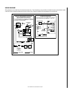
NOTE: DIAGRAMS & ILLUSTRATIONS NOT TO SCALE.
Figure 5
Figure 6
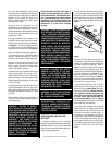
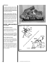
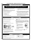
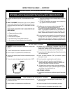
Pull the actuator forward to open the combus-
tion air door, and push it back to close. To "lock"
the combustion air door closed, ensure the
actuator is pushed all the way back, then push
the end of the actuators to the right until the
step in the actuator moves behind the appliance
front face within the slotted opening.
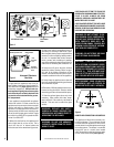
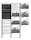
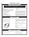
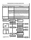
MANUALLY-RESET BLOCKED FLUE SAFETY
SWITCH
This appliance is equipped with a manually-
reset blocked flue safety switch. Refer to
Figure 7
for its location. If during appliance
operation, the flame goes out (independently
of the burner on/off wall switch), it may be due
to the operation of this safety limit switch.
First allow the appliance to cool, then reset
the safety switch by pushing the red reset
button on the back of the switch.
CAUTION: THE ELECTRONIC APPLIANCE
SHOULD BE TURNED OFF BEFORE REMOV-
ING THE LIMIT SWITCH.
To access the safety limit switch reset button,
remove the screen rod and screen from the
right side of the fireplace. Unscrew two screws
and remove the limit switch with low voltage
wires attached. Push the reset button, then
reinstall the limit switch. Reinstall the screen
and rod. At this time turn the electronic
appliance back on.
The appliance should then relight and remain
lit. If this does not occur, turn off the appli-
ance and call a qualified service technician.
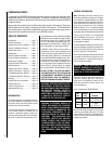
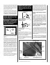
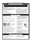
The control lever snaps into place at either
extreme of its range of motion. When locked
in position all the way to the right, the damper
is open. When locked in position all the way to
the left, the damper is closed.
The damper lever actuates a switch, (see wir-
ing diagram) which will prevent the appliance
main burner from lighting unless the damper
is locked open. The appliance flue damper
must always remain open when operating.
Remove Locking Screw
and “Pop” Actuator to the
Left Before Initial Use
Combustion Air
Actuator
Pull Forward to Open,
Push Back to Close
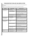
Many appliances are equipped when installed
with an outside (make-up) air vent system that
is designed to provide the appliance with out-
side make-up air for combustion when in
operation. The actuator for the outside air
system is standard on all appliances but must
not be operated if the complete system is not
installed. Refer to
Figure 6
. When the com-
plete outside air vent system is installed, the
installer will remove the actuator locking screw.
If your screw is not removed and you have
reason to believe that you have a complete
outside air system, contact your distributor to
have your appliance inspected for the pres-
ence of the complete system.
DO NOT assume that you have this system in
place because you have an actuating lever
present on your appliance front face.
Figure 7
Damper
Closed
Damper
Open
Lintel
Outside Air
Actuator
Limit Switch Screws
Manual
Reset
Limit
Switch
Screen
Rod
Lintel Extension Right Side Refractory Panel
Screen
To provide outside combustion air to your
appliance while it is in operation, locate the
combustion air actuator along the right side of
the appliance opening (
Figure 5
).
To operate, push the end of the actuator to the
left as shown in
Figure 6
, until it "pops" free of
its "locked" position.
WARNING: DAMPER MUST BE IN OPEN
POSITION WHEN APPLIANCE MAIN
BURNER IS OPERATING.
AVERTISSEMENT: LE REGISTRE DOIT
ÊTRE EN POSITION OUVERTE LORSQUE
LE OU LES BRULEURS PRINCIPAUX DE
L'APPEREIL FONCTIONNMENT.
WARNING: DO NOT OPERATE THE COM-
BUSTION AIR ACTUATOR UNLESS A
COMPLETE OUTSIDE AIR VENT SYS-
TEM HAS BEEN INSTALLED WITH YOUR
APPLIANCE.