6
NOTE: DIAGRAMS & ILLUSTRATIONS NOT TO SCALE.
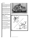
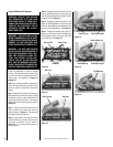
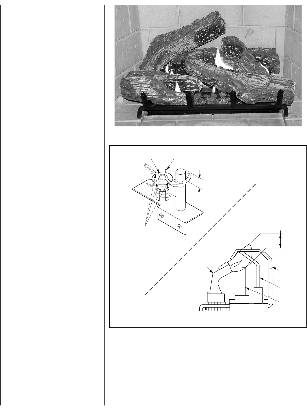
Figure 9
Figure 8
Maintenance
The appliance and venting system should be
thoroughly inspected before initial use and at
least annually by a qualified service techni-
cian. Proper maintenance and use will require
more frequent, less extensive inspections and
servicing by the homeowner.
Generally, annual inspections should be per-
formed by a qualified service technician. More
frequent periodic inspections and cleanings
should be performed by the homeowner. Any
discrepancies discovered by the homeowner
should result in a call to a qualified service
technician to effect the repair or correction.
Refer to the maintenance schedule for mainte-
nance tasks, procedures, periodicity and by
whom they should be performed.
IMPORTANT: TURN OFF GAS AND ANY
ELECTRICAL POWER BEFORE SERVICING
THE APPLIANCE.
Millivolt Appliance Checkout
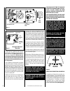
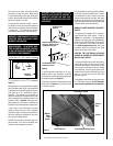
The pilot flame should be steady, not lifting or
floating. Flame should be blue in color with
traces of orange at the outer edge.
The top ³⁄₈" (9 mm) at the pilot generator
(thermopile) should be engulfed in the pilot
flame. The flame should project 1" (25 mm)
beyond the hood at all three ports
(Figure 9 ).
Electronic Appliance Checkout
Light the burner, refer to the Lightilng Instruc-
tions in this manual. Ensure the ignitor lights
the pilot. The pilot flame should engulf the
flame rod as shown in
Figure 9.
With proper care and maintenance, your ap-
pliance will provide many years of enjoyment.
If you should experience any problem, first
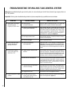
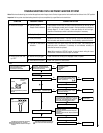
refer to the trouble shooting guide in this
manual. If problem persists, contact your
Superior distributor.
³⁄₈" Min
(9 mm)
Hood
Pilot
Nozzels
Ignitor Rod
Proper Flame
Adjustment
Hot Surface
Igniter
Flame Rod
Ground
Electrode
3/8 To 1/2 Inch
(9 mm to 13 mm)
Pilot
Nozzle
MILLIVOLT
ELECTRONIC


