


8 NOTE: DIAGRAMS & ILLUSTRATIONS ARE NOT TO SCALE
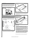
Insert the wall mounting screws into the top wall plugs, taking care
to leave the screws protruding approximately 3/8” from the wall. Now
hang the appliance onto these screws through the two keyhole shaped
holes in the back panel of the appliance.
Insert the lower mounting screws into the lower wall plugs through the
corresponding depressed holes in the lower part of the back panel. Do
not tighten fully.
Before tightening the wall mounting screws fully, at this stage it is
recommended to check the horizontal alignment of the appliance with a
bubble level, as small adjustments can still be made if necessary. When
this has been checked, tighten all four fixing screws fully.
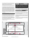
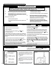
To access the upper fixing screws insert a screwdriver through the
holes in the deflector plates above the catalyst as shown in Figure 3.
12.0 CHECKING THE BURNER
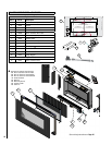
There are no imitation fuel bed components, such as logs or rocks,
to install. The appliance features a ribbon burner which is designed to
produce a continuous band of flame over its length. The burner should
be visually inspected to ensure it is free from any foreign matter. If it is
necessary to clean or dust off the burner then the glass door should be
removed by removal of the four retaining screws. Re-fit the glass door
after cleaning or inspection, ensuring a good seal.
13.0 CONNECTING A GAS LINE
11.0 MOUNTING THE APPLIANCE - continued
Figure 3
A qualified gas appliance installer must connect the gas room heater to
the gas supply. Consult all local codes.
The installer must provide an ANSI approved manual shut off valve, flex
connector and 3/8" NPT fitting. A flex gas line kit with shut-off valve is
available (see Page 16 or ordering information).
Route gas line using techniques and materials prescribed by local
and/or national codes. Only use pipe of 1/2" or greater size to allow full
gas volume to the gas fireplace. Undue pressure loss will occur if the
pipe is too small.
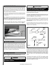
An external regulator must be used on all propane (L.P.G.) heaters, in
addition to the regulator fitted to the heater, to reduce the supply tank
pressure to 13" w.c. (maximum).
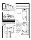
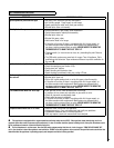
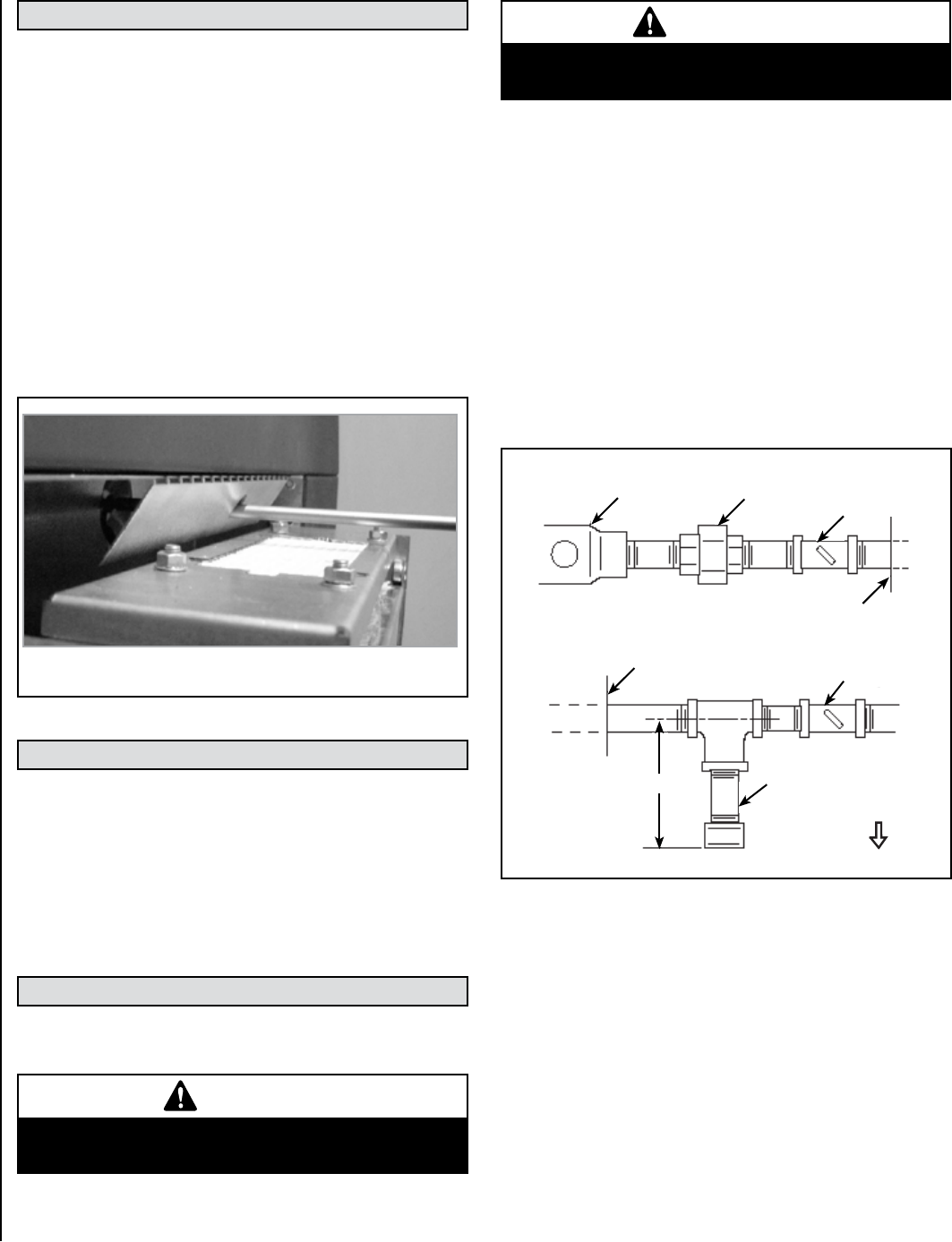
Regulator
Manual
Shut-Off
Valve
Union
Sediment
Trap
Fireplace or
Firebox Wall
Wall
Shut-Off
Key
Fireplace or
Firebox Wall
Down
3"
Figure 4
An ANSI approved manual shut-off valve and union must be installed
upstream of the heater within the fireplace cavity when rigid pipe is
used. Ensure that a sediment trap is installed upstream of the heater
(Figure 4) within the structure’s piping system to prevent moisture
and contaminants from passing through the pipe to the heater controls
and burner. Failure to do so could prevent the heater from operating
reliably.
The heater gas inlet connection is 3/8” NPT at the regulator, located
below the burner, in the right hand side of the heater. When tightening
up the joint to the regulator hold the regulator securely with a wrench
to prevent the regulator from moving.
IMPORTANT
Hold heater regulator with a wrench to prevent
movement when connecting to inlet piping.
WARNING
Connecting directly to a unregulated propane tank
may cause an explosion.
NOTE: See Page 19 for gas line entry point dimensions.