


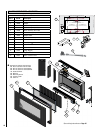
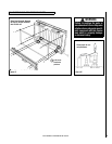
16
29.0 REPLACEMENT PARTS - SCANDIUM™
1
2
7
5
6
8
9a
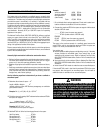
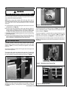
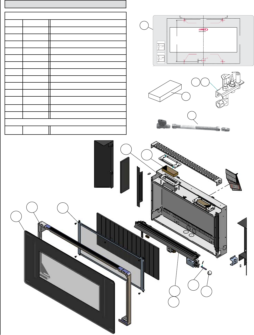
Replacement Parts
Item # Cat.No. Description
1 H6057 Glass door assembly
2 H6060 Catalyst
3 H6061 Pilot assembly, Natural Gas
4 H6999 Pilot assembly, Propane Gas
5 H6058 Burner Assembly, Natural Gas
6 H7012 Burner Assembly, Propane Gas
7 H6062 Catalyst Gasket
8 H7037 3 Pc. Frame Assembly
9a H7002 Ball Knob
9b H7041 Knob Spindle
10 H7006
Hardware Kit
u
11 H6068 Decorative Glass Facia
12 H7321 Fitting Template
Optional Parts
13 93L32 FFGC Flex Gas Line Kit
9b
11
12
u Hardware kits consists of the following:
6 ea. No.8 x 5/16 Screw Pozi Pan Head
6 ea. M6 x 12 Screw Pozi Pan Head BZP
6 ea. M4 x 12 Screw Pozi Pan Head Black
1 ea. Rubber Grommet
4 ea. Wall Plug
4 ea. Wall Fixing Screws
2 ea. Ceramic bracket
2 ea. Clevis Pin
See ordering instructions on Page 20
™
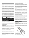
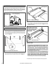
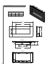
WARNING
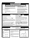
CLEARANCES FROMCOMBUSTIBLE MATERIALS
F860041/A
The following clearances must be maintained at all times.
Failure to do so may result in the risk of a fire.
For full information refer to the instruction manual
provided with the heater.
Note : Zero clearance from bottom of heater frame
required for hard combustible floors. Minimum 4”
clearance required to rugs or any fabric floor
coverings. REFER TO INSTRUCTION MANUAL
IMPORTANT : Fabrics, curtains and drapes are not
permited above the heater at any distance and within
20” of the heater sides. No combustible shelves of any
size are permitted above the heater.
Clearance to
combustible
sidewalls 4”
(both sides)
Clearance to combustible ceiling
32” measured from top of appliance
glass panel
Clearance in
front of
heater 20”
F860041/A
Deben mantenerse en todo momento los siguientes espacios
libres. El no hacerlo puede causar un riesgo de incendio.
Consulte el manual de instrucciones suministrado con este
aparato para obtener información completa.
Nota: No se requiere espacio libre desde el borde inferior del
marco del calentador en caso de pisos combustibles duros.
Se requiere un espacio mínimo de 4” entre el calentador y
cualquier alfombra, moqueta o revestimiento de suelo de
tela. CONSULTE EL MANUAL DE INSTRUCCIONES.
IMPORTANTE: No se permite la colocación de telas, cortinas y
similares por encima del calentador a cualquier distancia, ni a
una distancia de 20” de los laterales del calentador. No se
permiten estantes combustibles de cualquier tamaño por
encima del calentador.
Espacio hasta
paredeslaterales
combustibles
4” (ambos lados)
El espacio de 32” hasta un techo
combustible se mide desde el borde
superior del panel de vidrio del aparato
Espacio libre
delante del
calentador 20”
ADVERTENCIA
ESPACIO LIBRE HASTAMATERIALES COMBUSTIBLES
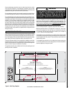
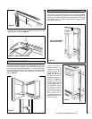
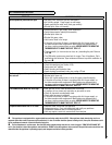
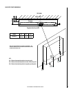
FIREBOX OUTLINE
CONTORNO DE LA CAMARA DE COMBUSTION
POSITION SPIRIT LEVEL ALONG THIS EDGE TO LEVEL TEMPLATE BEFORE MARKING OUT WALL
COLOQUE EL NIVEL SOBRE ESTE BORDE PARA NIVELAR LA PLANTILLA ANTES DE MARCAR LA PARED
PIERCE TEMPLATE TO MARK HOLE POSITION ON WALL X 4
CENTRE LINE
17-3/16” (437mm)
CONCEALED
GAS INLET
ENTRADA DE
GAS OCULTA
1/2”
(13mm)
16” (406mm)
FIXING POINTS
Scandium
FIXING POINTS
PUNTOS DE SUJECION
PERFORE LA PLANTILLA PARA MARCAR LA POSICION DE LOS 4 TALADROS EN LA PARED
PUNTOS DE SUJECION
LINEA DE CENTRO
WALL MOUNTED VENT FREE FITTING TEMPLATE
PLANTILLA PARA LA INSTALACION DE CHIMENEAS DE PARED SIN SALIDA DE HUMOS
IMPORTANT
THIS APPLIANCE IS TO BE WALL HUNG ONLY.
DO NOT RECESS OR INSET ANY PART OF THE APPLIANCE.
THIS TEMPLATE IS FOR THE MARKING OF FIXING POINTS ONLY.
DO NOT INSTALL THE APPLIANCE WITH THIS TEMPLATE IN PLACE.
IMPORTANTE
ESTE APARATO UNICAMENTE DEBE SER COLGADO EN UNA PARED.
NO EMPOTRE NINGUN ELEMENTO DE ESTE APARATO.
ESTA PLANTILLA SIRVE UNICAMENTE PARA MARCAR LOS PUNTOS DE FIJACION.
RETIRE LA PLANTILLA ANTES DE COLOCAR LE APARATO.
APPLIANCE OUTLINE CONTORNO DE LA APARATO
DO 005855/0 - ISSUE A
FocalPointFires Single 24/04/08 DO 005855/0 Lennox L40 Scandium fitting template
Ref. Paul West - Focal Point Fires. Any problems please call 01202 588629
Artwork Size: W1055 x H530
5
4
10
Hardware
4
3
13