


10 NOTE: DIAGRAMS & ILLUSTRATIONS ARE NOT TO SCALE
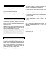
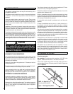
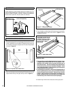
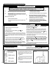
16.0 SPARK GAP
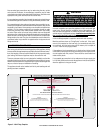
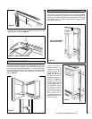
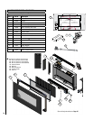
17.0 ASSEMBLY OF THE GLASS FACIA
Figure 9 - Proper Spark Gap
1/8" to 3/16" Spark Gap
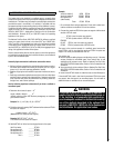
Figure 10 - Key Hole Slots on Glass Facia
1. Remove the glass panel from all packaging and lay face down on a soft
surface. Identify the top and bottom of the glass facia by observing
the orientation of the keyhole shaped slots in the facia fixing brackets
as shown in Figure 10.
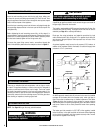
2. Slide on the side pieces ensuring that the grill fixing holes (shown) are
aligned towards the top of the glass facia (as shown in Figure 11).
Grill fixing holes
Figure 11 - Slide on Side Pieces
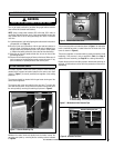
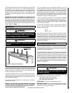
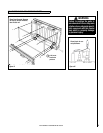
3. Ensure the sides are neatly aligned with the glass and secure the sides
using two M6 screws for each side as shown in Figure 12. Do not
overtighten the screws.
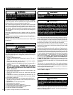
IMPORTANT NOTES:
• The screws that are used to attach the brackets to the facia as seen
in Figures 12 and 14 below MUST NOT be over-tightened. Over-
tightening of the mounting screws may cause the glass facia to
slip from its brackets. The screws should be finger-tightened until
all side and top frame pieces are assembled and aligned. At that
point, tighten the screws in 1/4 turn increments until frame pieces
are firmly positioned and do not move.
• If you find that your glass facia is experiencing slippage because of
this over-tightening of the screws, you can use normal RTV sealant
to secure the glass facia to its bracket. Remove the facia from the
fireplace, apply the sealant to the area where the slippage is oc-
curring, and allow the facia to dry face down until the sealant has
dried according to the directions on the sealant packaging.
4. Position the grill within the two side pieces ensuring a proper fit.
Figure 12 - Secure Side Pieces
TOP
Side Piece
The gap between the spark electrode and the pilot should be 1/8” to
3/16” to produce a good spark. There should be no need to adjust this
(DO NOT ATTEMPT TO ADJUST THE GAP). If under any circumstances
the piezo electric spark fails, the pilot cannot be lit manually.
Adjustment to the
pilot is Not allowed
Finger-tighten all screws until side
and top frame pieces are in place
and aligned. At that point, tighten in
1/4 turn increments until frame
pieces are secure. DO NOT
OVER-TIGHTEN.