


NOTE: DIAGRAMS & ILLUSTRATIONS ARE NOT TO SCALE
13
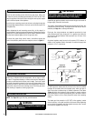
Clean the pilot assembly with a soft brush and blow through. Check the
aeration holes are free of any dirt or lint. Clean thoroughly internally,
the connection can be removed from the base of the pilot assembly
using two wrenches to make cleaning easier. Do not damage or try to
dismantle the pilot injector. The unit is factory set and the only check
necessary is to ensure the spark gap is correct. See specifications for
gas setting.
NEVER MODIFY OR BEND THE THERMOCOUPLE TO MAKE THE PILOT
STAY LIT. If the pilot will not stay lit there is a problem with dirt, the
gas supply, or the thermocouple needs replacement. Modifications are
dangerous and can have a serious unseen effect on safety and therefore
MUST not be done. Replacements must be original manufacturers parts.
Re-assemble in the reverse of removal. Ensure setting pressures are as
stated in Table 1 on Page 3.
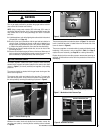
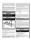
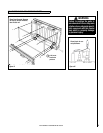
24.0 CATALYSTS
WARNING
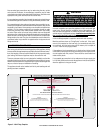
Do not block the catalysts or the appliance outlet grill.
Blockage may cause high carbon monoxide levels
and/or breakage of the glass facia panel.
Figure 18 - Catalysts and Outlet Grill
It is recommended that the catalysts are inspected for signs of damage
and dirt during routine servicing procedures. The expected life of the
catalysts is in excess of 11,000 hours (10 years of normal use). After
this time the catalyst should be replaced.
If there are any deposits of dirt or soot on the catalysts they should be
cleaned with a soft brush and a vacuum cleaner. If removed for cleaning
ensure the seals are in good condition before replacing the catalyst. New
seals will usually be required.
The performance of the catalyst may be checked using a combustion
gas analyzer as follows.
Important: The temperature of the gases emitted by the catalytic
converters reach very high temperatures (up to 700° F). Measuring
gas of this temperature may damage some types of gas analyzers. If
in doubt consult the equipment manufacturer.
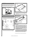
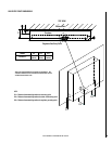
25.0 TESTING FOR FIREBOX LEAKAGE
Appliances that are several years old or have been extensively dismantled
should be checked for soundness. It is important that all the products
of combustion pass through the catalytic converters at the top of the
firebox before leaving the appliance.
The firebox is heated by lighting for a few minutes to provide a flow
through the firebox. The burner is then shut off and a smoke pellet or
match introduced at the base of the fire underneath the burner tray. Large
quantities of smoke will emerge from the top of the appliance, but none
should emerge from the joints or gasket faces, especially around the
door. It is important to note that the appliance can never be expected
to be 100% smoke tight and small quantities of smoke may be seen in
corners of joints and gasket faces etc without affecting safety when the
appliance is in operation.
Turn on the fireplace as per the operating instructions, and run at
maximum setting for 15 minutes. Position gas sample probe directly
over a catalyst via the outlet grill, on top of the appliance. Record the
carbon dioxide (CO
2) concentration and then the carbon monoxide (CO)
concentration as displayed by the analyzer - also noting the units in
which the values are expressed. Most analyzers display carbon dioxide
(CO2) concentrations in percentage (%) terms and carbon monoxide
concentration in parts per million (ppm) terms.
In order to calculate the combustion ratio for the appliance (CO/CO2)
it is first necessary to express both gas concentrations in terms of per-
centage. To convert from parts per million (ppm) to a percentage (%)
divide the ppm figure by 10,000. Examples : 35ppm = 0.0035%, 15ppm
= 0.0015%, 5ppm = 0.0005%.
Now divide the concentration of carbon monoxide (CO) expressed in
percent by the concentration of carbon dioxide (CO2) to obtain the
appliance combustion ratio.
CO (%)
CO2 (%) = ratio
The combustion ratio of the gasses emitted by the catalytic convertor
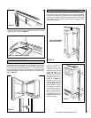
should not exceed 0.0015. If replacing, firstly, remove the glass facia
as described in section 16.0. The catalysts are located on the top of the
internal firebox and can be removed be unscrewing the retaining nuts
securing the clamping plate. Remove the catalysts and seals and discard.
Refit a new catalysts and seals in reverse order, ensure the catalysts
and door have good seals.
26.0 CLEANING
WARNING
Turn off the unvented gas room heater and allow to
cool before cleaning.
GLASS PANEL -This can be cleaned with a suitable glass cleaner. The
following solutions are approved for use to clean glass.
• Non-ammonia based household cleaner
• 50% -50% mix of white vinegar and water
• Gas fireplace/stove glass cleaner
PAINTED AREAS - These can be cleaned using a dry cloth.
FINISHED METAL AREAS - These can either be cleaned using a proprietary
metal cleaner or baby oil. Test on a small hidden part before cleaning.
Always clean in the direction of the grain.
WARNING
Do not operate the appliance with the catalyst units
removed.
DO NOT BLOCK
THESE AREAS