


2.0 GENERAL INFORMATION
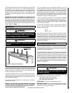
This appliance is a high efficiency, unvented, flame effect gas heater. It
provides radiant and convected warmth both efficiently and safely utilizing
the latest type catalytic convertor burner technology. The appliance does
not require a flue system of any type as the catalytic converter cleans
the flue products to provide a complete combustion system, which is
intrinsically safe.
3.0 PACKAGING LIST
Quantity Description
1 Firebox And Burner Assembly
1 Installation And Operation Instructions
1 Glass Facia Panel Assembly
1 Fitting Template
1 Screw And Wall Plug Pack
1 Rubber Grommet
4.0 APPLIANCE SPECIFICATIONS
CONGRATULATIONS!
When you purchased your new gas fireplace, you joined the
ranks of thousands of individuals whose answer to their home
heating needs reflects their concern for aesthetics, efficiency
and our environment. We extend our continued support to help
you achieve the maximum benefit and enjoyment available from
your new gas fireplace.
Thank you for selecting a Lennox Hearth Products gas fireplace
as the answer to your home heating needs.
TABLE OF CONTENTS
Section Contents Page No.
1.0 Safety And Warning Information
. . . . . . . . . . . . . 2
2.0 General Information
. . . . . . . . . . . . . . . . . . . . . . . 3
3.0 Packaging List
. . . . . . . . . . . . . . . . . . . . . . . . . . . 3
4.0 Appliance Specifications
. . . . . . . . . . . . . . . . . . . 3
5.0 Unpacking the Appliance
. . . . . . . . . . . . . . . . . . . 4
6.0 Burn-in Period
. . . . . . . . . . . . . . . . . . . . . . . . . . . 4
7.0 Codes, Massachusetts and New York
. . . . . . . . . 4
8.0 Combustion And Ventilation Air
. . . . . . . . . . . . . . 5
9.0 Site Requirements
. . . . . . . . . . . . . . . . . . . . . . . . 6
10.0 Preparing The Appliance
. . . . . . . . . . . . . . . . . . . 6
11.0 Mounting The Appliance
. . . . . . . . . . . . . . . . . . . 7
12.0 Checking The Burner
. . . . . . . . . . . . . . . . . . . . . . 8
13.0 Connecting A Gas Line
. . . . . . . . . . . . . . . . . . . . 8
14.0 Checking The Gas Connections
. . . . . . . . . . . . . . 9
15.0 Gas Pressure Check
. . . . . . . . . . . . . . . . . . . . . . . 9
16.0 Spark Gap
. . . . . . . . . . . . . . . . . . . . . . . . . . . . . . 10
17.0 Assembly of the Glass Facia
. . . . . . . . . . . . . . . . 10
18.0 Fitting the Glass Facia
. . . . . . . . . . . . . . . . . . . . . 11
19.0 Fitting the side panels
. . . . . . . . . . . . . . . . . . . . . 11
20.0 Briefing The Customer
. . . . . . . . . . . . . . . . . . . . . 12
21.0 Servicing
. . . . . . . . . . . . . . . . . . . . . . . . . . . . . . . 12
22.0 Servicing The Burner
. . . . . . . . . . . . . . . . . . . . . . 12
23.0 Pilot Assembly
. . . . . . . . . . . . . . . . . . . . . . . . . . . 12
24.0 Catalysts
. . . . . . . . . . . . . . . . . . . . . . . . . . . . . . . 13
25.0 Testing For Firebox Leakage
. . . . . . . . . . . . . . . . 13
26.0 Cleaning
. . . . . . . . . . . . . . . . . . . . . . . . . . . . . . . . 13
27.0 Lighting Instructions & Turning Off Appliance
. . . 14
28.0 Troubleshooting Guide
. . . . . . . . . . . . . . . . . . . . . 15
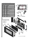
29.0 Replacement Parts List
. . . . . . . . . . . . . . . . . . . . 16
30.0 Positioning Of Field Assembled Parts
. . . . . . . . . 17
31.0 Specifications / Gas Entry Point Dimensions
. . . . 18
32.0 Product Reference Information
. . . . . . . . . . . . . . 20
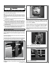
These heaters are fitted with a specially designed pilot utilizing an oxygen
depletion sensor (ODS) which responds to the amount of oxygen avail-
able in the room and shuts the heater off before the oxygen level drops
below 18%. It must not be adjusted or put out of operation. If replaced
then manufacturers original parts must be used. The pilot can be relit
only when fresh air is available. Refer to the Combustion and Ventilation
Air section.
The appliance is designed to fit various types of situations as listed in
the installation requirements.
This appliance is factory set for operation on the gas type, and at the
pressure stated on the appliance rating plate.
Read all these instructions before commencing installation. All instructions
must be left in the possession of the user for safekeeping.
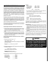
Gas Type Natural Gas Propane Gas
Gas inlet pressure Max.
Min.
10.5” w.c.
6” w.c.
13” w.c.
11” w.c.
Regulator Pressure Setting 5” w.c. 10” w.c.
Max Energy Input 11,950 BTU/hour 10,235 BTU/hour
Min Energy Input 6,820 BTU/hour 6,820 BTU/hour
Pilot Energy Input 560 BTU/hour 560 BTU/hour
Burner Pressure High
(Manifold) Low
2.4” w.c.
0.8” w.c.
5.5” w.c.
2.4” w.c.
Main burner flow restrictor
(burner orifice)
2.0 mm (0.079”) 1.45mm (0.057”)
Oxypilot SIT/Bray 9082 SIT/Bray 9284
Gas Inlet Connection 3/8” NPT at regulator 3/8” NPT at regulator
Ignition Piezo spark Piezo spark
Spark Gap 1/8” - 3/16” 1/8” - 3/16”
Please see Data Plate affixed to appliance for current data. This appliance is for use
only with the gas type, and at the pressure stated on the appliance Data Plate.
Table 1
3