


11
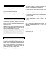
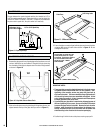
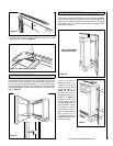
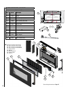
5. Secure the grill in position using two M6 screws and two no. 8 self
tapping screws as shown in Figure 14.
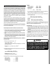
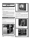
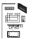
18.0 FITTING THE GLASS FACIA
The glass facia panel is supported by four M6 screws which protrude
from the front of the outer casing. Insert the M6 retaining screws and
ensure they are unscrewed approximately 1/8” so the keyhole shaped
holes may engage, and the facia can be hooked on. Ensuring that the
corresponding keyhole shaped holes engage the screw-heads fully.
Refer to Figure 15.
Figure 15
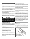
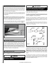
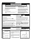
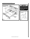
19.0 FITTING THE SIDE PANELS
Remove the two side panel assemblies from the protective packaging
and fit onto the sides of the firebox as shown. Insert the M6 retain-
ing screws in the sides of the firebox and ensure they are unscrewed
approximately 1/8” so the keyhole shaped holes may engage, and the
sides can be hooked on.
Note : Front frame/facia
not shown for clarity.
Insert a screwdriver
through the holes in the
right hand side panel to
access the two M6 fixing
screws (designated ‘a’ in
Figure 17) and tighten
fully. Next insert two no.8
self-tapping screws (des-
ignated ‘b’ in Figure 17)
through the side panel
support bracket, and the
corresponding holes in the
side of the firebox. Tighten
fully. Repeat for the left
hand side panel, which is
secured by tightening the
M6 ‘a’ screws only. The
right-hand side panel has a
hinged flap to allow access
to the control knob.
Figure 13
Figure 14 - Secure Grill In Position
Figure 16
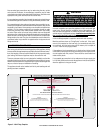
NOTE: DIAGRAMS & ILLUSTRATIONS ARE NOT TO SCALE
TOP
‘a’
‘a’
‘b’
‘b’
Figure 17