


NOTE: DIAGRAMS & ILLUSTRATIONS ARE NOT TO SCALE
5
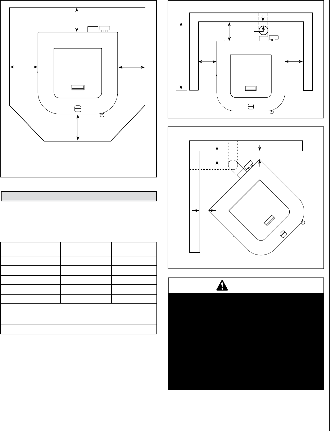
Up to * 6” (153 mm)
6”
(153 mm)
min.
6”
(153 mm)
min.
6” (153 mm)
min.
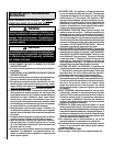
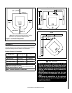
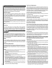
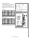
Figure 1 - Floor Protection Requirements
*Note:
When installed at clearances less than 6”, the floor
protection is only required to extend to the wall.
Rear
Front
Top View
Floor Protector
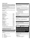
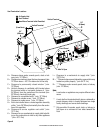
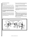
Standard residential or manufactured home installation. These appliances
require the following minimum clearances to combustibles:
Minimum Clearances To Combustibles
Figure 2
Combustible
Combustible
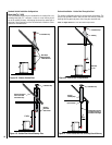
Montage 32FS
Horizontal Flue –
Directly Through Wall
Interior Vertical
Flue
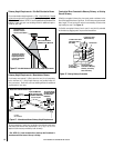
A - Side wall to unit
u 4” (102 mm) u 4” (102 mm)
B - Back wall to unit
2” (51 mm)
9” (229 mm)
C - Side wall to unit Corner 1” (25 mm) 1” (25 mm)
D - Max. Depth of Alcove
v 24” (610 mm) v 24” (610 mm)
E - Flue to Wall 3” (77 mm) 3” (77 mm)
u Measured to fuel hopper lid in alcove.
v Minimum Alcove Measurements - Height 48” (1220 mm) x Width 31”
(788 mm) x Maximum Depth 24” (610 mm)
Table 1 - Minimum Clearances To Combustibles
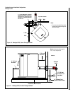
Combustible
Rear Wall or Alcove
Figure 3
Corner
B
A
E
D
A
E
C
C
Combustible
Combustible
IMPORTANT
•
Minimum clearances specified may not allow
for ease of operation and maintenance (please
take this in to account when planning the instal
-
lation). If installed to the minimum clearances,
removal of the appliance may be necessary for
servicing.
•
Recommended clearance zone from the front
of the appliance to combustibles is 4 feet mini
-
mum.
•
Clearances to combustibles for the appliance
can only be reduced by means approved by the
regulatory authority.
CLEARANCES
FPO
FPO