


11
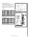
NOTE: DIAGRAMS & ILLUSTRATIONS ARE NOT TO SCALE
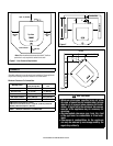
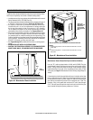
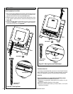
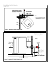
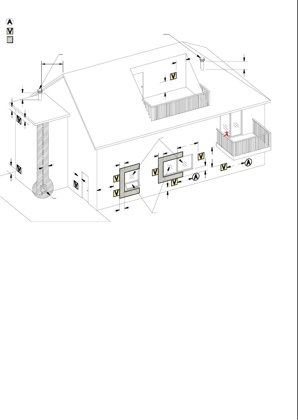
Vent Termination Locations
A = Clearance above grade, veranda, porch, deck, or bal-
cony (min. 12”/30cm)
B = Clearance to window or door that may be opened (min.
12”/30cm above - 48”/1.2m below and to the side)
C = Clearance to permanently closed window *(min.
12”/30cm)
D = Vertical clearance to ventilated soffit located above
the terminal within a horizontal distance of *(min.
24”/60cm) from the centerline of the terminal (min.
22”/55cm) check with local code.
E = Clearance to unventilated soffit *(min. 12”/30cm)
F = Clearance to outside corner *(min. 12”/30cm)
G = Clearance to inside corner *(min. 12”/30cm)
H = Not to be installed above a meter/regulator assembly
within *(min. 36”/90cm) horizontally from the center-
line of the regulator.
J = Clearance to service regulator vent outlet *(min.
72”/1.8m)
K = Clearance to non-mechanical air supply inlet to build
-
ing or the combustion air inlet to any other appliance
*(min. 48”/1.2m)
L = Clearance to a mechanical air supply inlet *(min.
120”/3.1m)
M = **Clearance above paved sidewalk or a paved driveway
located on public property *(min. 84”/2.1m)
N = ***Clearance under veranda, porch, deck, or balcony
(min. 12”/30cm)
Note:
* Local codes or regulations may require different clear
-
ances.
** A vent shall not terminate directly above a sidewalk or
paved driveway which is located between two single
family dwellings and serves both dwellings.
*** Only permitted if veranda, porch, deck, or balcony is
fully open on a minimum of two sides beneath the
floor.
Vent Terminal
Area Where Terminal Is Not Permitted
(From Eave)
Vertical Terminal
Vertical Terminal
Fixed Closed
Able To Open
A
A
B
B
B
B
C
D
E
F
G
H
J
K
L
M
N
24”
(610mm)
B
Air Supply Inlet
24”
(610mm)
Figure 9