14
Connect the Gas Supply
Gas Supply Requirements
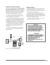
ALL INSTALLATIONS MUST COMPLY WITH LOCAL
CODE OR IN THE ABSENCE OF LOCAL CODE, MUST
COMPLY WITH THE MOST RECENT EDITION OF THE
NATIONAL FUEL GAS CODE ANSI Z223.1/NFPA 54 OR
CAN-B149.
Shutoff Valve
All codes require a gas shutoff valve (gas cock)
and union to be installed in the supply line and in
the same room as the appliance. This allows for the
disconnection of the fireplace for servicing and
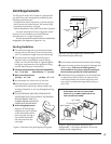
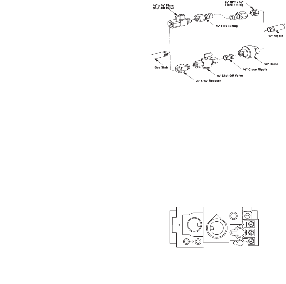
maintenance. See fig. 25.
A T-handle gas shutoff valve is required in
Massachusetts in compliance with Code 248CMR.
The fireplace and gas control valve must be
disconnected from the gas supply piping during any
pressure testing of the system at test pressures in
excess of 1/2 psig. For pressures lower than 1/2 psig,
isolate the gas supply by closing the manual shutoff
valve.
Control Valve Connection
The gas supply line connection is made to the
left side of the valve. The gas supply line should be a
minimum 3/8" diameter, or the appropriate size to
provide sufficient gas pressure to the valve regard-
less of the input setting.
The use of flexible gas appliance connectors is
acceptable in many areas in the U.S. In Canada,
methods vary depending on local code. If local codes
permit, use flexible gas line for ease of installation
and service. For those locales where flexible gas
lines are not permitted, use the 3/8” iron fitting to
make the connection at the left side of the Control
Valve. See Figures 25 and 26.
Secure all joints tightly using appropriate tools
and sealing compounds (for propane units, be sure
to use compounds that are propane resistant). Turn
on gas supply and test for gas leaks using a soapy
water solution. Never use an open flame to check
for leaks.
Leak test:
• Mix a 50-50 solution of water and dish soap.
• Light appliance- see lighting instructions on page
23 of this manual or on the fireplace’s rating
plate.
• Brush or spray all joints and connections with the
soapy water solution.
• If bubbles appear at any connection or seam or a
gas odor is detected, immediately turn gas
control knob to the OFF position.
Tighten or reconnect the leaking joint and retest
for any gas leaks.
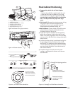
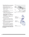
Figure 25. Gas supply line fittings.
Gas Pressure
Proper gas pressure provides a consistent flow
of gas to the appliance and is instrumental in
checking for gas leaks. The gas control valve on the
fireplace is equipped with pressure test points for
gauge connections. The gauge connections are
located on the front of the valve under the On/Off/
Pilot knob. Gauge connections are identified by:
• IN/E for inlet or supply pressure (the amount of
gas coming to the valve.)
•OUT/A for manifold pressure (the amount of gas
that is coming out of the valve to the burner.)
EA
Figure 26. Pressure test point as located on the
front of the valve.


