13
Final Cabinet Positioning
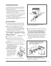
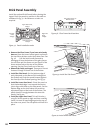
1. If appropriate, attach the 4/6 Vent Adaptor
Collar:
• Remove the 5/8 Collar supplied with the unit.
• Align the 4/6 Collar as shown in fig. 23 and
secure to the unit using the original screws. Be
sure the single round fastener hole is oriented to
the 12 o-clock position for proper vent align-
ment.
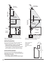
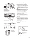
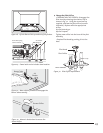
1. Side Standoffs: Remove the retainer screws. Using
vise grips or pliers, fold each standoff at the
perforations. Secure each standoff using the
screws previously removed. See fig. 24.
2. Wall Stud Brace: Loosen, bend, and position each
cabinet Retainer Strap for attachment to the
fireplace enclosure. See fig. 24.
3. Locate the fireplace cabinet in its final position
within the enclosure. Confirm that the first 45°
Elbow is correctly aligned for final vent assembly
and secure it to the Vent Collar using 3, #10 sheet
metal screws.
4. Confirm that the cabinet is positioned to align its
forward edge with the finished surface of the
wall facing. The stud braces allow approximately
2 inches of forward adjustment to accommodate
most any facing thickness. Secure the braces to
the enclosure frame.
5. Complete the gas line and electrical power
routing as appropriate for blower and thermo-
stat functions.
Figure 24. Standoff and Stud Brace orientation.
Remove, bend and
reattach each Wall
Stud Brace.
Remove, bend and
reattach each Standoff.
Standoff in shipping position.
Figure 23. 4/6 Vent Collar orientation.
For correct vent pipe
alignment, be sure the
round hole is oriented to
the 12- o’clock position
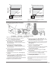
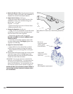
Figure 20. Blower Kit 155630 contents.
Figure 21. Blower location.
Figure 22. Install snapstat bracket and switch box.
5
3
2
1
1. #129374 Fan/Motor Unit- 125 cfm., variable speed
2. #220012 Base Plate
3. #220637 Snapstat (140°F - 120°F)
4. #220989 Snapstat Bracket
5. #220055 Rubber Grommets, 4
6. #9930 M6 Hex Flange nuts, 2
4
6
BLOWER
IGNITOR
HI
LO
AUTO
MANUAL
OFF
ON
OFF
BURNER
AUT
O
MAN
U
OF
F
HI
LO
Snapstat Bracket
6


