


Secure all joints tightly using appropriate tools
and sealing compounds (for propane units, be sure
to use compounds that are propane resistant).
Turn on gas supply and test for gas leaks using a
soapy water solution. Never use an open flame
to check for leaks.
Leak test:
· Mix a 50-50 solution of water and dish soap.
· Light appliance- see lighting instructions on
page 23 of this manual or on the stoves rating
plate.
· Brush or spray all joints and connections with
the soapy water solution.
· If bubbles appear at any connection or seam
or a gas odor is detected, immediately turn
gas control knob to the OFF position.
Tighten or reconnect the leaking joint and retest
for any gas leaks.
GAS PRESSURE:
Correct gas pressure is essential for efficient and
safe operation of the Allagash gas stove. It is
important that the correct pressure is established
at the time of the installation.
Proper gas pressure provides a consistent flow of
gas to the appliance and is instrumental in
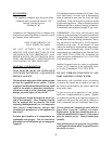
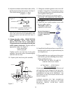
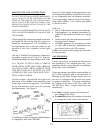
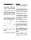
checking for gas leaks.The gas control valve on
the stove is equipped with pressure test points
for gauge connections. The gauge connections
are located on the front of the valve under the
On/Off/Pilot- knob. Gauge connections are
identified by:
E for inlet or supply pressure (the amount of
gas coming to the valve.)
A for manifold pressure (the amount of gas that
is coming out of the valve to the burner.)
MAKING THE GAS CONNECTION:
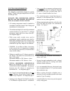
NOTE: IF THE OPTIONAL FORCED BLOWER KIT
(PART # 129161) IS TO BE INSTALLED ON THE
STOVE AT THE TIME OF THE INSTALLATION
OR IN THE FUTURE, THE GAS SUPPLY LINE
SHOULD BE INSTALLED AS CLOSE TO THE
FLOOR AS POSSIBLE.
USE OF A 90° ELBOW DIRECTLY OFF THE VALVE
WILL ALLOW FOR PROPER CLEARANCE FOR
THE BLOWER.
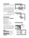
The gas supply line connection is made to the valve
just inside the left rear leg. The Gas supply line
should be a minimum of 3/8" in diameter, or
the appropriate size to provide sufficient gas
pressure to the valve regardless of the input
setting.
The use of Flexible Gas Appliance Connectors is
acceptable in many areas in the U.S.; However,
Canadian methods vary depending on local code.
ALL INSTALLATIONS MUST COMPLY
WITH LOCAL CODE OR IN THE ABSENCE
OF LOCAL CODE, MUST COMPLY WITH
THE MOST RECENT EDITION OF THE
NATIONAL FUEL GAS CODE ANSI Z223.1/
NFPA 54 OR CAN-B149.
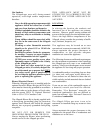
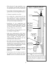
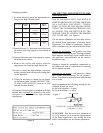
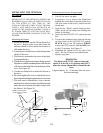
All codes require: a gas shut-off valve (gas cock)
and union, to be installed in the supply line, and
in the same room as the appliance. This allows
for the disconnection of the stove for servicing
and maintenance. See Figure 5.
Figure 5
T-handle gas cocks are required in Massachusetts
in compliance with code 248CMR.
EA
Pressure test point as located on the front of the valve.
12