


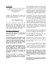
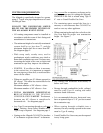
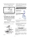
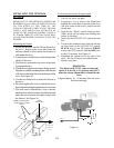
8. Adjust the air shutter on the burner tube to allow
for the proper mixing of air and gas. See Figure 2.
The correct settings: natural 1/4 open
propane
1/4 open
WHEN RE-INSTALLING THE BURNER TUBE BE SURE
THAT THE TUBE IS PULLED FORWARD IN THE
MOUNTING HOLES, SECURE WITH THE TWO 1/4
SCREWS.
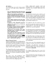
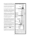
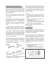
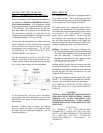
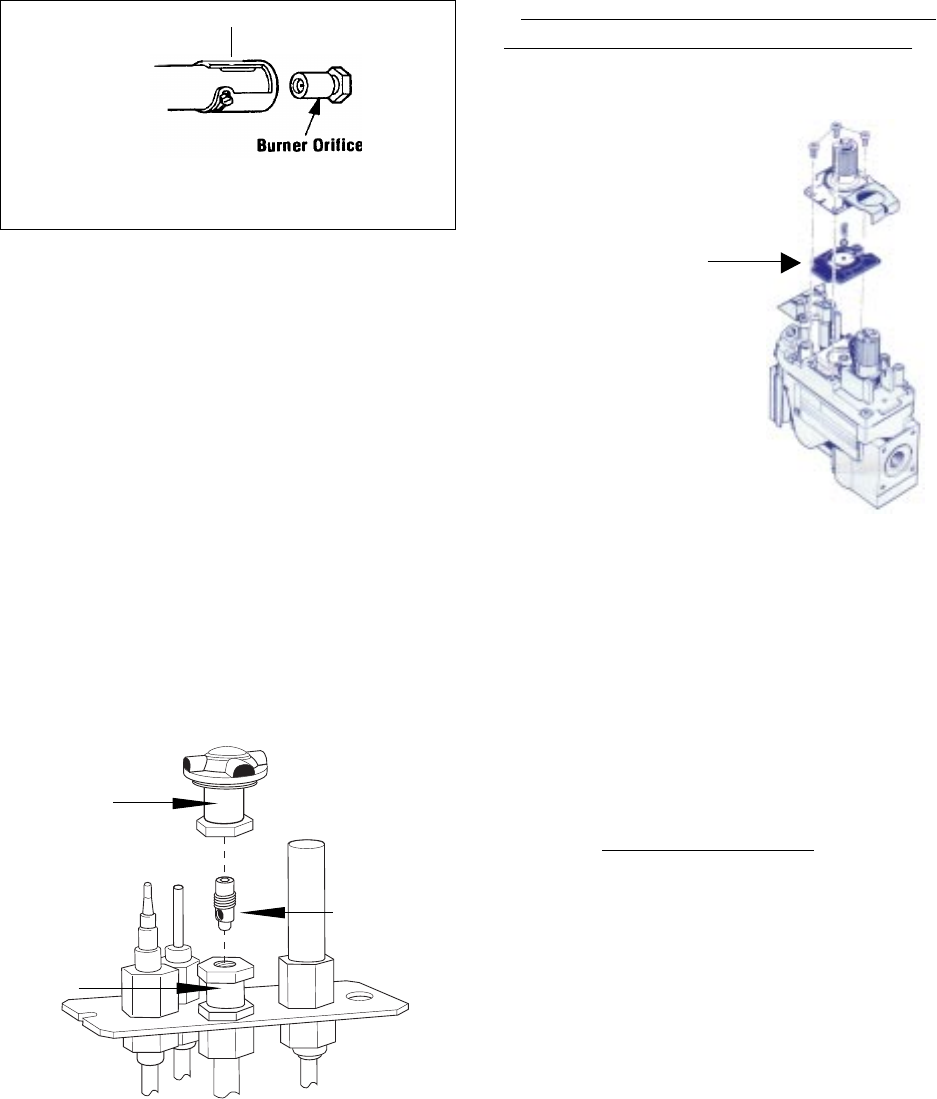
9. Change the pilot orifice. FROM WITHIN
THE FIREBOX, PULL THE PILOT
HOOD OFF THE PILOT ASSEMBLY.
Using a 4mm allen wrench thread out the pilot
orifice (counter clockwise). Replace with the
appropriate orifice: See Figure 3.
#51or natural gas
#30 for propane
Tighten orifice into the base of the pilot
assembly. Be sure the orifice is threaded tightly
and flush with the base.
10. Replace pilot hood onto pilot assembly.
14. Install the identification labels to the stove so
that they can be seen by any person that may be
servicing the stove.
15. Reassemble the stove, apply gas to the system
and check for gas leaks including all stove lines
before and after the valve.
NEVER USE AN OPEN FLAME TO
CHECK FOR GAS LEAKS.
ATTENTION!! ATTENTION!!
This is very important
Correct gas pressure is essential for efficient and
safe operation of the Allagash B-Vent gas stove.
It is important that the correct gas pressure be
established at the time of the installation. For
more details, see the Gas Pressure section of this
manual on page 13.
ALWAYS REFER TO THE LIGHTING
INSTRUCTIONS ON PAGE 23 OF THIS
MANUAL WHEN LIGHTING YOUR
ALLAGASH.
11
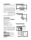
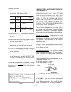
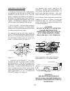
11. Change the variable regulator on the valve (Hi/
Lo knob). Using a Torx t-20 screwdriver, remove
the three specialty screws from the front of the
valve regulator. See Figure 4.
12. Remove the regulator tower and the gasket.
BE SURE TO REMOVE THE BLACK
RUBBER GASKETS FROM THE VALVE!!!
See Figure 4.
13. Install the new variable regulator tower with
the new rubber gasket.
Thoroughly tighten new
regulator to valve body.
BURNER TUBE
AIR SHUTTER
ATTENTION: Air shutter should never be
LESS than 1/8 open.
Figure 2
Figure 4.
BE SURE TO REMOVE
THE BLACK RUBBER
GASKET FROM THE
VALVE!!!
Figure 3.
PILOT HOOD
PILOT ORIFICE
SCREWS
INTO
BASE
PILOT
ORIFICE