


536636-UIM-D-1211
Johnson Controls Unitary Products 7
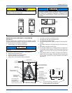
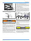
DRAIN CONNECTIONS
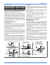
All drain lines should be trapped a minimum of three inches, should be
pitched away from unit drain pan and should be no smaller than the coil
drain connection.
Route the drain line so that it does not interfere with accessibility to the
coil, air handling system or filter and will not be exposed to freezing
temperatures. See Figures 2 and 3 for drain connection locations.
Coils should be installed level or pitched slightly toward the drain end.
Suggested pitch should not exceed 1/4 inch per foot of coil.
The coil is provided with a secondary drain that should be trapped and
piped to a location that will give the occupant a visual warning that the
primary drain is clogged. If the secondary drain is not used it must be
capped. When an exterior secondary drain pan is used that secondary
drain should br piped to a location that will give the occupant a visual
warning that the primary drain is clogged.The drain pan connections are
designed to ASTM Standard D 2466 Schedule 40. Use 3/4" PVC or
steel threaded pipe. Since the drains are not subject to any pressure it
is not necessary to use Schedule 40 pipe for drain lines.
DO NOT use teflon tape, “pipe dope” or other sealants. The use of a
sealant may cause damage and premature failure of hte drain pan
SECTION IV: ELECTRIC HEATER
INSTALLATION
If the air handler requires electric heat, install the electric heat kit
according to the installation instructions included with the kit. After
installing the kit, mark the air handler nameplate to designate the heater
kit that was installed. If no heater is installed, mark the name plate
appropriately to indicate that no heat kit is installed.
The HEAT/ENABLE jumper (See Figure 10) must be moved to the
HEAT position to enable operation of the heater.
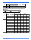
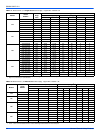
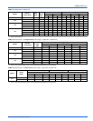
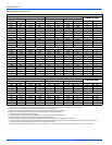
Use only 4HK heater kits, as listed on Air Handler name plate and in
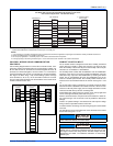
these instructions. Use data from Tables 10 and 13 for information on
required minimum motor speed tap to be used for heating operation,
maximum over-current protection device required and minimum electri-
cal supply wiring size required – for listed combination of Air Handler
and Heater Kit.
For Upflow, Downflow and Horizontal right hand applications the kits
can be installed without modification.
Field modification is required for Horizontal left hand airflow application
only. Follow instructions with heater kits for modification.
SECTION V: LOW VOLTAGE CONTROL
CONNECTIONS
This air handler can be connected to the wall thermostat and outdoor air
conditioner or heat pump using either conventional low voltage (24
VAC) thermostat wiring OR using four-wire digital communications wir-
ing. To use conventional low voltage wiring, see the section below enti-
tled “Conventional Low Voltage Control Wiring”. To use four-wire
communications control wiring, see the section below entitled “Control
Wiring using Communicating Controls”.
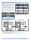
The Communicating System consists of several intelligent communicat-
ing components including the Communicating Thermostat Control
(touch-screen wall thermostat), variable speed air handler, air condi-
tioner (15 and 18 SEER premium air conditioners) or heat pump (13, 15
and 18 SEER premium heat pumps), which continually communicate
with each other via a four-wire connection called the A-R-Gnd or C-B
bus. Commands, operating conditions, and other data are passed con-
tinually between components over the A-R-Gnd or C-B bus. See Figure
13. The result is a new level of comfort, versatility, and simplicity.
In order to use this air handler in full communications (COMM) mode, it
MUST be installed with the matching touch-screen Communicating
Control (wall thermostat) and an outdoor air conditioner or heat pump
with a fully communicating control.
This air handler may also be used along with the Communicating Ther-
mostat Control and a non-communicating outdoor air conditioner
through the addition of a communicating Outdoor Aux Control board to
the outdoor unit. This system allows full communication between the air
handler and thermostat and limited communication to the outdoor unit.
This air handler may also be used along with the Communicating Ther-
mostat Control and a non-communicating outdoor air conditioner or
heat pump using COMM between the air handler and thermostat and
conventional 24V wiring to the outdoor unit. This system allows full
communication between the air handler and thermostat but no digital
communication with the outdoor unit. See Figure 14.
Threaded drain connection should be hand-tightened, plus no more
than 1/16 turn.
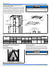
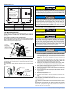
When the coil is installed in an attic or above a finished ceiling, an
auxiliary drain pan should be provided under the coil if specified by
local building codes.
NOTICE
If a heat kit with a circuit breaker is installed in the air handler, the cir-
cuit breaker cover cladding must be removed to gain access to the
sheet metal cover plate. Some local codes may require that the circuit
breaker remain visible. If so, do not re-install circuit breaker cover
cladding.
NOTICE
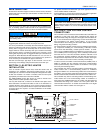
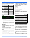
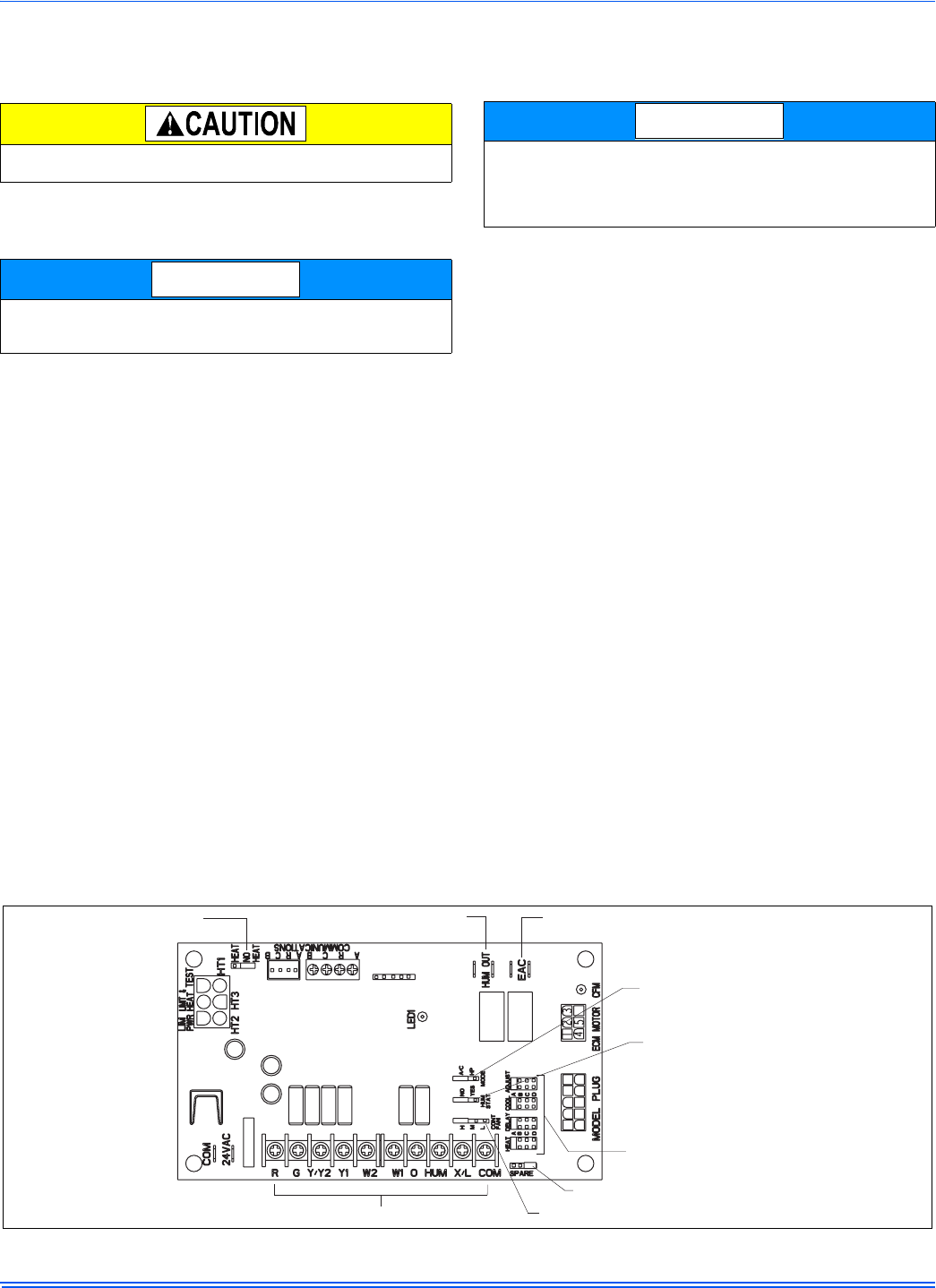
FIGURE 11: Air Handler Control Board – Communications Connections
SPARE JUMPER
HEATENABLE JUMPER
HUMIDIFIER OUT PUT
EAC OUTPUT
THERMOSTAT CONNECTIONS
CONTINUOUS FAN JUMPER
BLOWER SPEED
JUMPERS
HUMIDSTAT
JUMPER
AC/HP JUMPER