


536636-UIM-D-1211
Johnson Controls Unitary Products 5
DUCT CONNECTIONS
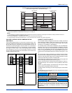
Air supply and return may be handled in one of several ways best
suited to the installation. See Figure 3 for dimensions for duct inlet and
outlet connections.
The vast majority of problems encountered with combination heating
and cooling systems can be linked to improperly designed or installed
duct systems. It is therefore highly important to the success of an instal-
lation that the duct system be properly designed and installed.
Use flexible duct collars to minimize the transmission of vibration/noise
into the conditioned space. If electric heat is used, non-flammable
material must be used.
Where return air duct is short, or where sound may be a problem,
sound absorbing glass fiber should be used inside the duct. Insulation
of duct work is a must where it runs through an unheated space during
the heating season or through an uncooled space during the cooling
season. The use of a vapor barrier is recommended to prevent absorp-
tion of moisture from the surrounding air into the insulation.
The supply air duct should be properly sized by use of a transition to
match unit opening. All ducts should be suspended using flexible hang-
ers and never fastened directly to the structure. This unit is not
designed for non-ducted (freeblow) applications. Size outlet plenum or
transition to discharge opening sizes shown in Figure 3.
Duct work should be fabricated and installed in accordance with local
and/or national codes. This includes the standards of the National Fire
Protection Association for Installation of Air-Conditioning and Ventilat-
ing Systems, NFPA No. 90B.
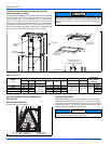
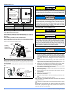
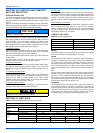
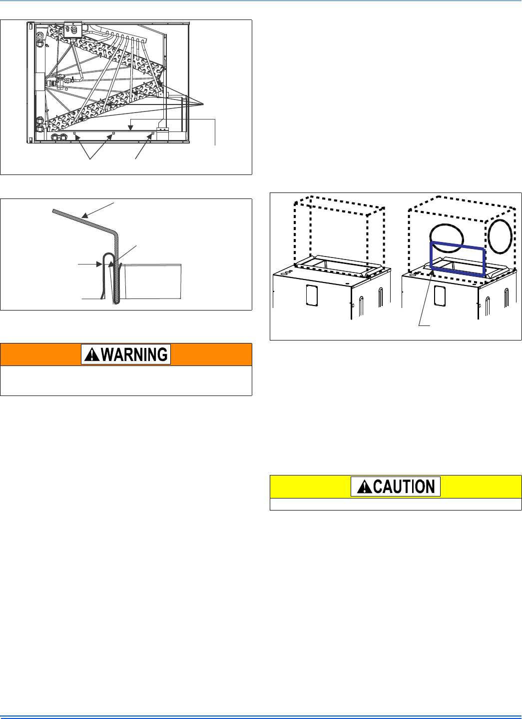
DUCT WORK TRANSITION
Duct work that is not designed to match the supply air opening can
cause turbulence inside the plenum box. This turbulence can change
the air flow patterns across the heat kit limit switch. If the factory sug-
gested transition can not be fabricated, it is recommended a block off
plate (approximately 8” in height and running the full width of the ple-
num) be attached to the supply opening Please refer to Figure 7 as a
visual aid. The use of this block off plate will keep better air circulation
across the limit switch.
The above suggestions will not alleviate problems caused by improper
installation. When receiving intermittent fault codes pertaining to the
limit switch, always double check your airflow CFM, motor speed and
static pressures.
AIR FILTERS
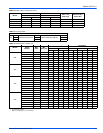
Air filters must be field supplied. A 1" filter access rack has been built
into the unit. See Figure 3. Remove filter access cover shown. Install
proper size filter. Standard 1" size permanent or throw away filter may
be used, or, permanent washable filters are available using model num-
bers: 1PF0601, 602, 603BK. See Table 8 for filter size.
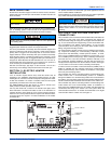
HORIZONTAL SUSPENSION (AV ONLY)
For suspension of these units in horizontal applications, it is recom-
mended to use angle steel support brackets with threaded rods, sup-
porting the units from the bottom, at the locations shown in Figure 8.
When an evaporator coil is installed in an attic or above a finished ceil-
ing, an auxiliary drain pan should be provided under the air handler as
is specified by most local building codes.
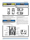
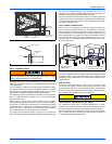
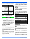
FIGURE 5: Condensate Deflecctor on Horizontal Drain Pan Edge
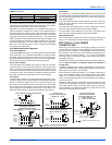
FIGURE 6: S-Clip Installation
Use 1/2" screws to connect ductwork to bottom of unit. Longer screws
will pierce the drain pan and cause leakage. If pilot holes are drilled,
drill only though field duct and unit bottom flange.
S-CLIPS ON HORIZONTALPAN
FEEDER
TUBES
CONDENSATE
DEFLECTOR
DEFLECTOR
S-CLIP
DRAIN PAN
WALL
FIGURE 7: Duck Work Transition
Equipment should never be operated without filters.
SUGGESTED LOCATION
OF BLOCK OFF PLATE
RECOMMENDED
TRANSITION