


536636-UIM-D-1211
Johnson Controls Unitary Products 3
DOWNFLOW AND HORIZONTAL CONVERSION
(AV ONLY)
These air handler units are supplied ready to be installed in a upflow
and right hand horizontal position. If unit requires left hand positioning,
the unit must have the coil assembly repositioned.
1. Remove blower, coil, and filter access panels.
For downflow and horizontal left installations, follow steps 2 - 8.
2. Remove tubing connection panel.
3. Remove front drain pan, hold down bracket.
4. Slide coil assembly out of air handler.
5. Rotate cabinet 180º so blower outlet is facing down.
6. Re-install coil assembly on downflow bracket.
7. Re-attach front drain pan, hold down bracket.
8. Re-attach tubing connection panel.
9. For horizontal applications, rotate air handler 90º into desired ori-
entation.
10. Re-position drain plugs as necessary based on air handler orienta-
tion.
11. Re-position and replace access panels.
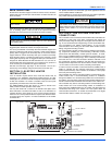
12. For downflow installations, the cladding should be reconfigured so
that the grille and circuit breaker covers having logos and/or black
coloring are at the top of the unit on the coil access panel. See
below.
13. Apply branding label to air handler in recessed area provided on
blower access panel cladding. This label should be applied after
the air handler is placed in its proper orientation so the label is
right side up.
When an evaporator coil is installed in an attic or above a finished
ceiling, an auxiliary drain pan should be provided under the coil as is
specified by most local building codes.
In severe high humidity, high temperature indoor unit environments,
an accessory insulation blanket is available to supplement the stan-
dard cabinet insulation. Insulate with UPG Kit: 1VJ0117 for B cabi-
nets, 1VJ0121 for C cabinets or 1VJ0124 on D cabinets or seal
completely with adequate fiberglass insulation using vapor barrier on
the outside.
NOTICE
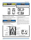
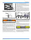
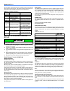
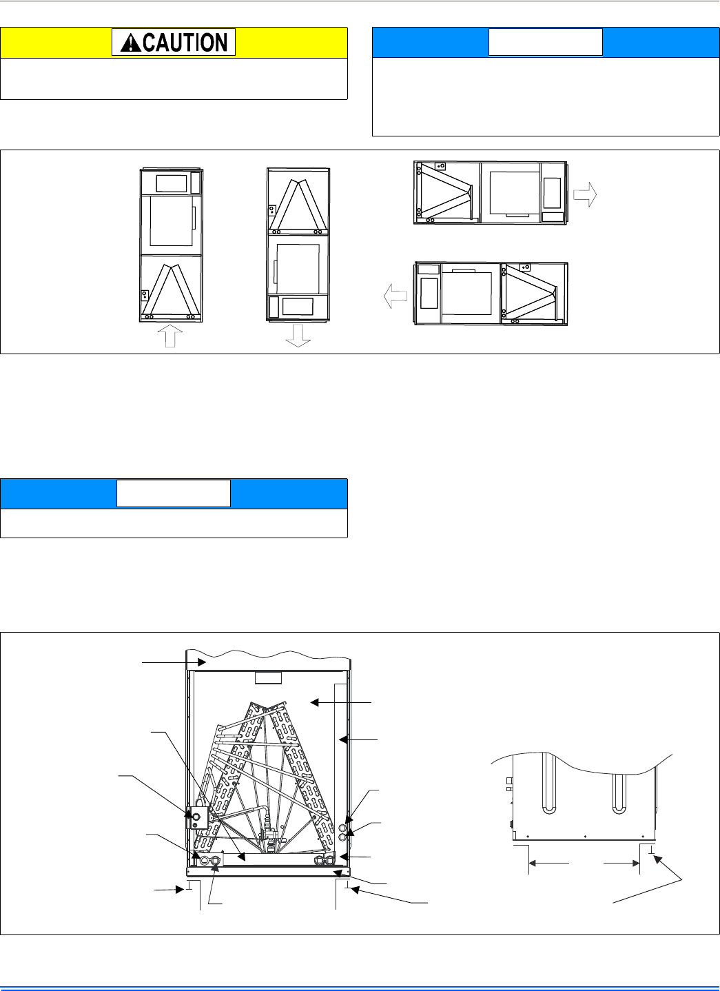
FIGURE 1: Typical Installation
UPFLOW DOWNFLOW
HORIZONTAL RIGHT
HORIZONTAL LEFT
Conversion must be made before brazing the refrigerant connections
to the coil.
NOTICE
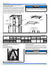
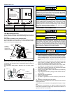
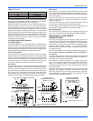
FIGURE 2: Return Duct Attachment & Component Location
FRONT VIEW
SIDE VIEW
BLOWER
COMPARTMENT
VERTICAL
DRAIN PAN
REFRIGERANT LINE
CONNECTIONS
PRIMARY DRAIN
UPFLOW 3/4”
THREADED
DUCT WORK MAY
BE FASTENED
CAUTIOUSLYWITH
SCREWS TO THE
SIDESAND REAR OF UNIT
SECONDARY DRAIN
UPFLOW 3/4” THREADED
COIL COMPARTMENT
(Access panel removed)
HORIZONTAL
DRAIN PAN
HORIZONTAL
SECONDARY DRAIN
HORIZONTAL
PRIMARY DRAIN
ALTERNATE
DRAIN CONNECTIONS
UPFLOW/DOWNFLOW
FILTER DOOR
RETURNAIR
DUCT
WHENATTACHING DUCT WORK WITH
SCREWS - KEEP SCREWS WITHIN 5/8”
OF SIDESAND BACK OF AIR HANDLER