


536636-UIM-D-1211
16 Johnson Controls Unitary Products
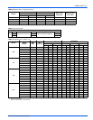
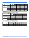
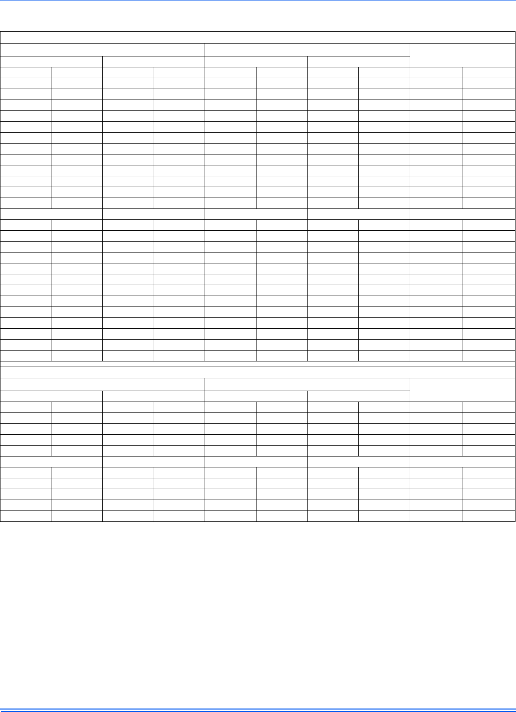
TABLE 16:
Air Handler Air Flow Data
HIGH/LOW SPEED COOLING AND HEAT PUMP AIRFLOW
CFM
m
3
/min
JUMPER SETTINGS
24B 36C 24B 36C
High Low High Low High Low High Low COOL Tap ADJ Tap
1088 707 1387 905 30.8 20.0 39.3 25.6 A B
830 542 1151 753 23.5 15.3 32.6 21.3 B B
948 617 1201 783 26.8 17.5 34.0 22.2 A A
716 465 1009 657 20.3 13.2 28.6 18.6 B A
854 556 1086 703 24.2 15.7 30.7 19.9 A C
612 462 953 622 17.3 13.1 27.0 17.6 C B
637 460 901 588 18.0 13.0 25.5 16.6 B C
531 460 754 493 15.0 13.0 21.3 14.0 D B
542 462 831 540 15.3 13.1 23.5 15.3 C A
462 462 657 460 13.1 13.1 18.6 13.0 D A
474 460 751 494 13.4 13.0 21.3 14.0 C C
461 464 588 461 13.1 13.1 16.6 13.1 D C
48D 60D 48D 60D JUMPER SETTINGS
High Low High Low High Low High Low COOL Tap ADJ Tap
2138 1442 2364 1545 60.5 40.8 66.9 43.7 A B
1759 1162 1962 1271 49.8 32.9 55.5 36.0 B B
2009 1311 2123 1374 56.9 37.1 60.1 38.9 A A
1612 1052 1763 1146 45.6 29.8 49.9 32.4 B A
1773 1166 1905 1237 50.2 33.0 53.9 35.0 A C
1530 989 1777 1158 43.3 28.0 50.3 32.8 C B
1459 947 1580 1021 41.3 26.8 44.7 28.9 B C
1359 886 1596 1030 38.5 25.1 45.2 29.2 D B
1388 904 1583 1019 39.3 25.6 44.8 28.8 C A
1221 806 1413 929 34.6 22.8 40.0 26.3 D A
1244 808 1412 926 35.2 22.9 40.0 26.2 C C
1118 715 1277 841 31.6 20.2 36.2 23.8 D C
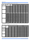
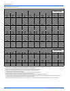
HIGH/LOW SPEED ELECTRIC HEAT AIRFLOW
CFM
m
3
/min
JUMPER SETTINGS
24B 36C 24B 36C
High Low High Low High Low High Low HEAT Tap ADJ Tap
1088 828 1387 908 30.8 23.4 39.3 25.7 A Any
954 714 1228 804 27.0 20.2 34.8 22.8 B Any
829 614 1151 756 23.5 17.4 32.6 21.4 C Any
678 523 923 609 19.2 14.8 26.1 17.2 D
48D 60D 48D 60D JUMPER SETTINGS
High Low High Low High Low High Low HEAT Tap ADJ Tap
2111 1417 2363 1488 59.8 40.1 66.9 42.1 A Any
1858 1252 2174 1252 52.6 35.4 61.5 35.4 B Any
1480 985 1868 1061 41.9 27.9 52.9 30.0 C Any
1250 840 1387 823 35.4 23.8 39.3 23.3 D Any
1. Airflow at nominal voltage, bottom return at 0.5 external static pressure, tested without filter installed, dry coil conditions.
2. These units have variable speed motors that automatically adjust to provide constant CFM from 0.0” to 0.6” w.c. static pressure
3. From 0.6” to 1.0” static pressure, CFM is reduced by 2% per 0.1” increase in static.
4. Operation on duct systems with greater than 1.0” w.c. external static pressure is not recommended.
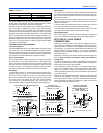
5. Both the COOL and the ADJUST tap must be set to obtain the cooling airflow desired (CFM).
6. The ADJ tap does not affect the HEAT tap setting.
7. Low speed cooling used only with two stage outdoor units. (Speed is preset to 65% of high speed).
8. Dehumidification speed is 85% of jumper selected COOL tap and ADJUST tap.
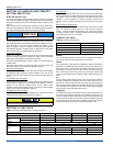
9. When operating in both heat pump and electric heat modes, the airflow (CFM) will be per HEAT Tap CFM values only.
10. At some settings, LOW COOL and/or LOW HEAT airflow may be lower than what is required to operate an airflow switch on certain models of electronic air
cleaners. Consult the instructions for the electronic air cleaner for further details.
11. Airflow (CFM) indicator light (LED2) flashes once for every 100 CFM (i.e.: 12 Flashes is 1200 CFM) – blinks are approximate +/- 10% of actual CFM.