


536636-UIM-D-1211
4 Johnson Controls Unitary Products
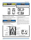
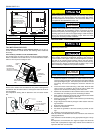
CLADDING CONFIGURATION FOR DOWNFLOW
INSTALLATION (IF USED)
To reconfigure the cladding parts, remove the grille by pulling gently at
the top. Once the grille is removed, the circuit breaker cover can also be
removed. Remove the gray, non-branded grille and circuit breaker
cover from the cladding on the coil access panel. Next, remove the
black and/or branded grille and circuit breaker cover from the blower
access panel. Install these pieces into the coil access panel cladding so
they are at the top of the air handler. Install the gray, non-branded grille
and circuit breaker cover in the blower access panel cladding.
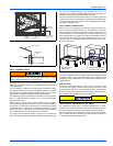
SUCTION FEEDER TUBE CONDENSATE
DEFLECTOR
UPFLOW OR DOWNFLOW
No action required. See Figure 4.
Horizontal Left or Right
Use an appropriate tool to pry out water deflector with two or three s-
clips from the vertical drain pan. See Figure 4. Relocate the deflector
with s-clips on the Horizontal Drain Pan lined up to the coil support
brackete. See Figure 5. This positions the deflector below the feeder
tubes to channel the condensate to the drain pan.
If a heat kit with a circuit breaker is installed in the air handler, the cir-
cuit breaker cover cladding must be removed to gain access to the
sheet metal cover plate. Some local codes may require that the circuit
breaker remain visible. If so, do not re-install circuit breaker cover
cladding.
NOTICE
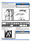
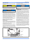
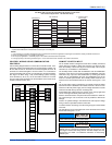
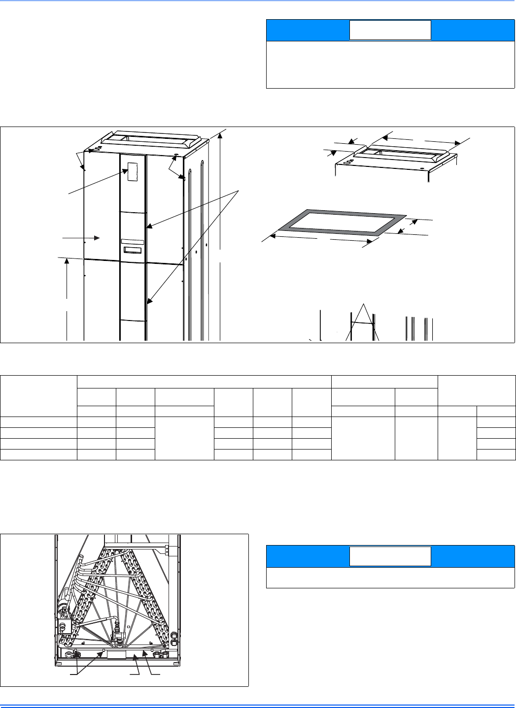
FIGURE 3: Dimensions & Duct Connection Dimensions
10-3/8”
F
CIRCUIT
BREAKER
PANEL
BOTTOM INLET
DIMENSIONS
BLOWER
COMPARTMENT
REFRIGERANT
DRAIN CONNECTIONS
FOR UPFLOWAND
DOWNFLOWAPPLICATIONS
D
A
E
TOP OUTLET
DIMENSIONS
18-9/32”
J
K
CLADDING
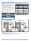
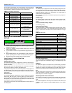
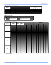
TABLE 1:
Dimensions
Models
AV
Dimensions (Inches)
Wiring Knockouts
1
Refrigerant
Connections
Line Size
AB C
DEF
JK
Height Width Depth Power Control Liquid Vapor
24B 46 17 1/2
21-1/2
(w/o cladding)
22-1/2
(with cladding)
12-3/8 13-29/32 14-19/32
7/8” (1/2”)
1 3/8” (1”)
1 23/32” (1 1/4”)
7/8” (1/2”) 3/8”
3/4”
36C 52 21 17-1/8 17-13/32 18-3/32 7/8”
48D 57 24 1/2 22-1/8 20-29/32 21-19/32 7/8”
60D 57 24 1/2 22-1/8 20-29/32 21-19/32 7/8’
1. Actual size (Conduit size).
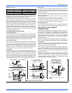
FIGURE 4: Condensate Deflector on Vertical Drain Pan
CONDENSATE
DEFLECTOR
S-CLIPS (3)
VERTICAL
DRAIN PAN
The condensate deflector should be installed in the s-clip section
which is inside the drain pan edge. See Figure 6.
NOTICE