


536636-UIM-D-1211
10 Johnson Controls Unitary Products
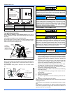
The low voltage connections may be connected to the screw terminals
or the quick connect terminals. The screw terminals and the quick con-
nect terminals are physically connected on the control board.
SECTION VI: REQUIRED CONTROL
SET-UP
1. Consult system wiring diagram to determine proper thermostat
wiring for your system.
2. If heat kit is installed, change HEAT/NO HEAT jumper from NO
HEAT to HEAT position.
3. If a humidistat is installed, change HUM STAT jumper from NO to
YES.
4. Set the MODE jumper to A/C (Air Conditioner) or HP (Heat Pump)
position depending on the outdoor unit included with the system.
5. Set airflow and comfort setting jumper to proper positions.
FUNCTIONALITY AND OPERATION
Jumper Positions
HEAT/NO HEAT Jumper
The HEAT/NO HEAT jumper configures the control for heat kit opera-
tion. The jumper must be in the HEAT position if a heat kit is installed
with the air handler.
With the jumper in the NO HEAT position, the control will not energize
the heat relay outputs or sense the limit switch input.
If the jumper is not present, the control will operate as if the jumper is in
the HEAT position. If the jumper is not present and a heat kit is not pres-
ent, the control will sense an open limit condition and the blower will run
continuously.
Hum Stat Jumper
The HUM STAT jumper configures the control to monitor the humidity
switch input. With the jumper in the NO position, the control will ener-
gize the HUM terminal with 24 VAC continually. With the jumper in the
YES position, the control will monitor the HUM input to control the HUM
OUT output to control an external humidifier.
If the jumper is not present, the control will operate as if the jumper is in
the YES position.
Mode Jumper
The MODE jumper configures the control to operate properly with an air
conditioner (AC position) or heat pump (HP position). With the jumper in
the AC position, the control will energize the O terminal with 24 VAC
continually. With the jumper in the HP position, the O input signal is
received from the room thermostat.
If the jumper is not present, the control will operate as if the jumper is in
the HP position.
SPARE Jumper
The control includes a spare jumper that can be used if a jumper is lost.
The SPARE jumper does not have any effect on the operation of the
control.
Airflow and Comfort Setting Jumpers
See separate section.
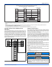
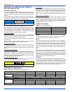
Status and Fault Codes
The control includes an LED that displays status and fault codes. These
codes are shown in Table 4. The control will display the fault codes until
power is removed from the control or the fault condition is no longer
present.
External Relay Outputs
The control includes two outputs to drive external relays having 24 VAC
coils. The outputs have a maximum rating of 1.0 Amp pilot duty at 24
VAC.
HUM OUT
The HUM OUT output can be used to drive an external relay or solenoid
(24 VAC coil) to control a humidifier. The output is energized when the
HUM input is energized, the HUM STAT is in the YES position, and the
control has a thermostat call for heating (heat pump or electric heat).
EAC
The EAC output can be used to drive an external relay (24 VAC coil) to
control an electronic air cleaner. The output is energized whenever the
blower relay on the control is energized.
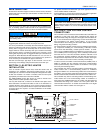
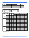
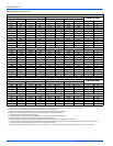
Heat Output and Limit Connections
The control is connected to the heater relays and limit switch using the
6-pin connector. The relay outputs and the limit switch signal are 24
VDC.
The control energizes the heat relays and senses the limit switch input
as shown in Table 5 when the HEAT ENABLE jumper is in the HEAT
position.
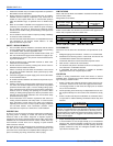
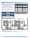
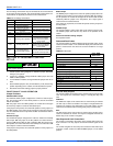
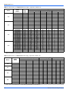
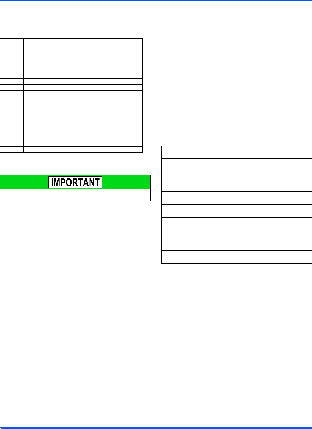
TABLE 3:
Low Voltage Connections
Terminal Signal Comment
R 24 VAC power (fused)
G Continuous Fan operation
Y/Y2
Second or full stage
compressor operation
Y1
First stage compressor
operation
Not used with outdoor units
having one stage compressors.
W2 Second stage heat operation
W1 First stage heat operation
O Reversing valve operation
24 VAC will be present at this
terminal when the MODE
jumper is in the AC position.
This is normal.
HUM Humidity switch input
24 VAC will be present at this
terminal when the HUM STAT
jumper is in the NO position.
This is normal.
X/L
Connection point for
heat pump fault indicator
This terminal is a connection
point only and does not affect
air handler control operation.
COM 24 VAC common
The following steps must be taken at the time of installation to insure
proper system operation.
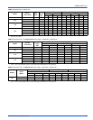
TABLE 4:
Fault Codes
Fault or Status Condition
LED1 (RED)
Flash Code
Status
No power to control OFF
Normal operation 2s ON/2s OFF
Control in test mode Rapid Flash
Control failure ON
Limit Faults
Limit switch currently open (not in lockout) 1
Multiple limit openings with no call for heat 2
Multiple limit openings during one call for heat 3
Single long duration limit opening 4
Multiple long duration limit openings 5
Fan failure 6
Wiring Related Faults
Simultaneous call for heating and cooling 7
Internal Control Faults
Control recovered from internal event 9